Two power supplies in the TS 2068 provide the 5 volts necessary for the computer’s CPU, ROM, RAM, SCLD, logic chips, and 12 volts for the video modulator.
The primary power supply uses the LM78S40 switching voltage regulator to produce 5 volts. This voltage regulator has an op amp that drives the internal speaker.
The secondary power supply uses the LM78L12 linear regulator to produce 12 volts.
Replacing both power supplies will improve video signal quality.
What You’ll Need
There are at least two ways to replace the stock power supplies. We can replace the 5 volt switching power supply with a modern LM7805 DC to DC converter. Some options include:
- CUI Inc. P78E05-1000
- Recom Power R78E5.0-1.0
- Traco Power TSR 1-2450
All three provide clean 1 amp at 5 volt power.
The 12 volt power supply does not need as much amperage. 500 milliamps is more than enough. Any of these three will work:
- CUI Inc. VX78012-500
- Mornsun America K7812-500R3
- XP Power VR05S12
I’ve linked to Digi-Key but you can get these from Mouser and other suppliers.
Another option is a single module that provides both 5 and 12 volts. In this tutorial, I’m using a ND4012DA module. It’s available from Amazon, on eBay and many other places. It provides 12 volts at 500ma and 5 volts at 1 amp.
You’ll also need:
- a soldering iron
- solder
- solder wick
- 4 short pieces of wire, about 4″ long
- electrical tape
- nippers
- needle nose pliers
- and a voltage/ohm meter
Let’s Get Started
Start by placing your TS 2068, keyboard down, on your work surface. Remove the screws that hold the case closed. There are three long screws along the back, and four short screws along the front.
Grab the computer, holding the case closed, and turn it back over. From the front, gently lift the top shell, like a clam. You can open it about 5-6 inches. Reach inside, grasp the flexible ribbon keyboard connector on both sides and gently pry it from the connector on the PCB.
Lift the top shell off and set it aside.
Next, remove the screws that hold the circuit board in place. There should be three: one near the power switch, one between two RAM chips and one near the right joystick connector.
Once you’ve removed the screws, lift the circuit board out and set the bottom shell aside.

Remove Existing Power Supply Parts
First, we’re going to disable the existing 5 volt internal power supply. You can cut all these parts off the board, except where noted.
- Start by removing Q1, the D43C1 power transistor. Unscrew the nut, remove the screw and heat sink, then cut off each of the legs, close to the circuit board.
- Remove CR1. Cut the right leg close to the board. Desolder the left leg. Use solder wick to remove the remaining solder.
- Remove R1 (blue ceramic, brown-brown-silver), a large blue power resistor.
- Remove R2 (blue-grey-black).
- Remove R4 (orange-orange-brown).
- Remove R5 (orange-orange-red-brown-brown).
- Remove R6 (brown-brown-black-brown-brown).
- Remove R9 (blue-red-orange).
- Remove capacitor C36 (green mylar).
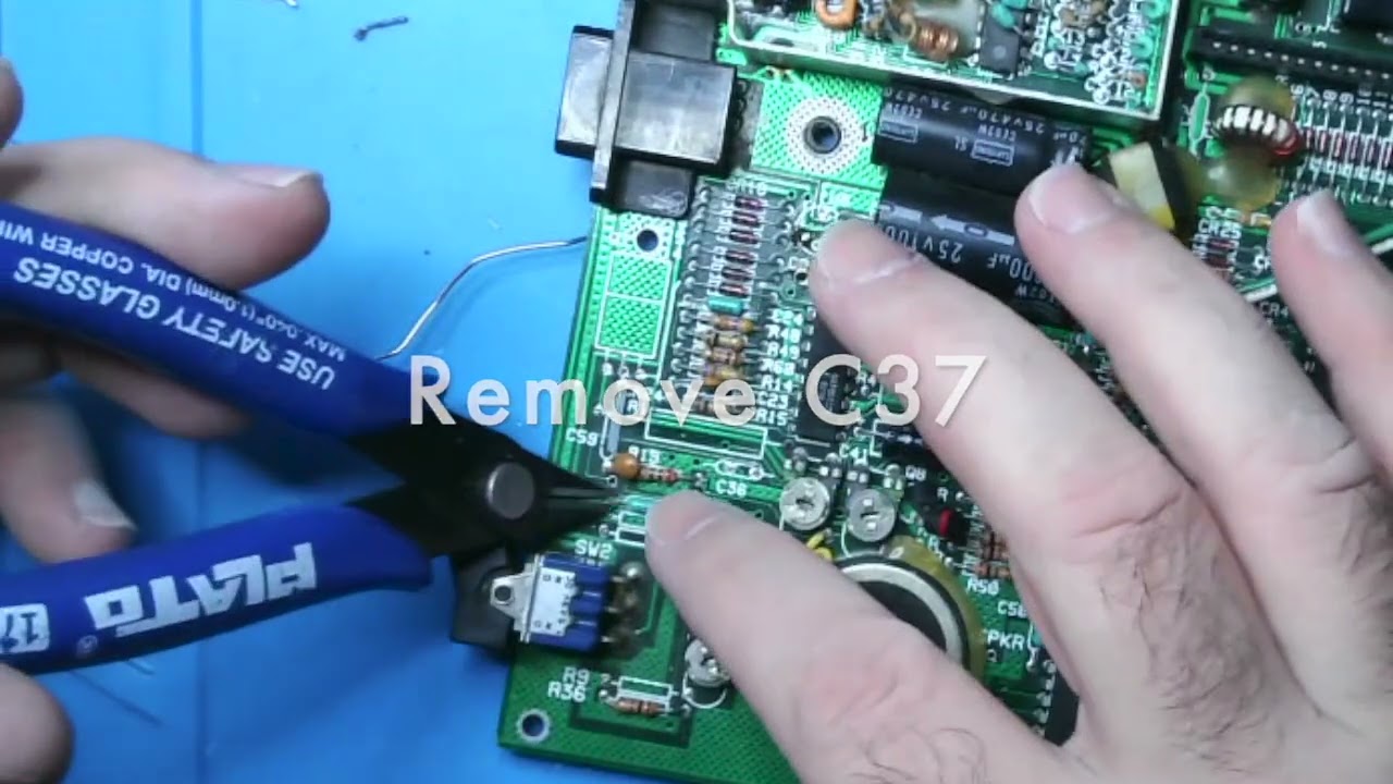
- Remove C37 (green tubular).
- Remove C59 (ceramic disk).
Next, we’ll remove the U8, the LM78L12 12 volt regulator.
- Remove U8 by cutting the top and middle legs, close to the circuit board.
- You can either cut the remaining leg, close to the device or grab the device with pliers as you desolder.
- Desolder the leg closest to the CR1 label. Use solder wick to remove the remaining solder.
You have removed all the parts required to disable the stock power supply.
Connect Your Replacement Supply

We’re using the ND4012DA module to power the TS 2068.
- Solder four short wires, about 4 inches long to O1, I, G and O2.
- Solder the wire from I to the bottom leg of the power switch.
- Solder the wire from G to the back tab of the power jack.
- Solder the wire from O1 to the bottom hole of the U8.
- Solder the wire from O2 to the left-most hole of CR1.
- Put a small piece of electrical tape on the bottom side of the module, covering your solder points.
Test Your Work
Clear your work surface of all the small bits of wire and connect the TS 2068 circuit board to a monitor.
Plug the power supply in to the jack and turn the computer on.
If you don’t immediately see the Sinclair/Timex copyright notice, turn off your computer and trace all the connections with your voltage/ohm meter.
What About The Speaker?
The internal speaker is driven by the op amp in the LM78S40 and we’ve just removed all power from it.
You can power just the op amp portion by connecting it to the 12 volt supply.
- Cut pin 5 of LM78S40 as close to the circuit board as you can.
- Bend up the pin.
- Solder a short wire to the pin.
- Solder the other end of the wire to the 12 volt wire of your supply.