The Timex/Sinclair 2068 is full of design compromises and shortcomings and the quality of the video signal is one the most annoying.
When it was new and connected to a TV, the RF modulator and overall poor bandwidth of TVs did a lot to mask the problem.

2068 owners had two alternatives: composite video or RGB. In theory, composite video should have been an improvement over a TV. In practice, the signal quality and display were not dramatically different.

RGB monitors supported higher resolution and displayed better than TVs were available at the time the 2068 was released. Timex anticipated the potential for connecting an RGB monitor to the 2068 by incorporating those signals on the edge connector. The Technical Manual even included a schematic for building a circuit to make the connection.
Unfortunately, RGB monitors have gone the way of the dinosaur. Modern LCD displays support composite, S-Video, VGA, HDMI and other signals. But 9 or 15 pin RGB connectors are non-existent.

Ancient Computer, Modern Solution
Inspired by Don Superfo’s Harlequin projects, I looked into the Analog Devices AD724 RGB to NSTC/PAL Encoder chip. The AD724 can turn the RGB signals, with a composite sync, into S-Video and composite video.
I combined the sync extractor schematic from the technical manual and the example from the AD724 documentation into one schematic and made a printed circuit board. The traditional method is to build this up on a breadboard first and confirm that it works, but the schematic and PCB design process is so easy, cheap and fast that I skipped ahead a bit.
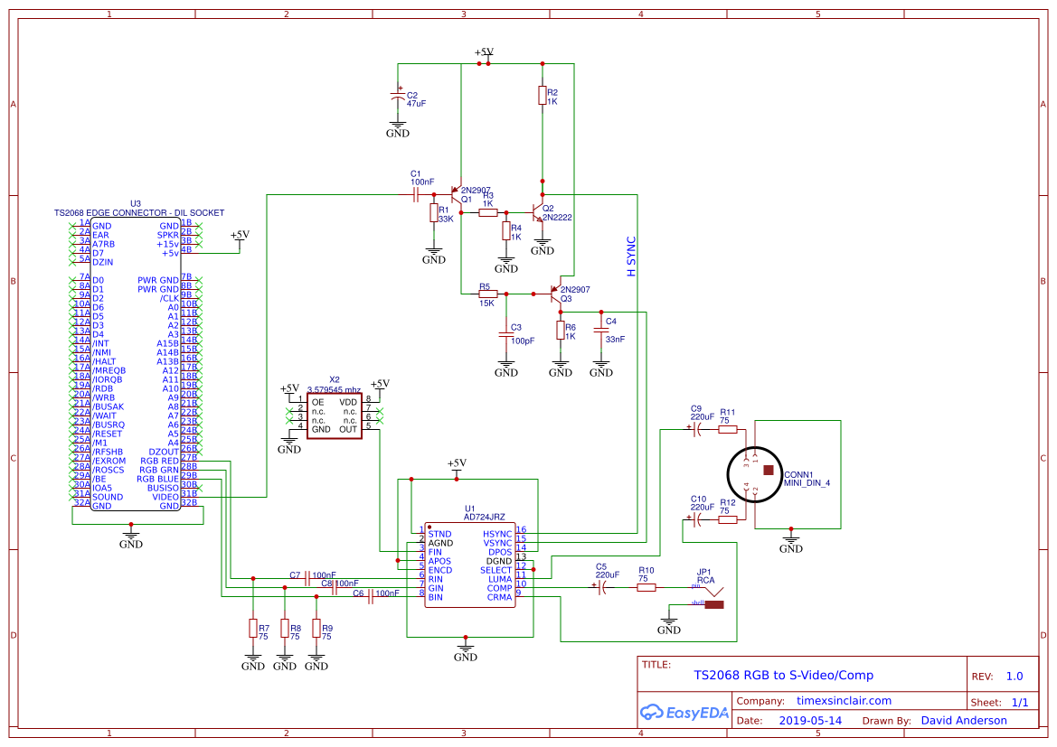


This schematic and PCB worked ok, generating a much cleaner video signal (missing all the noise) but shifted to the right on my monitor. I think the issue may be the signals from the sync separator portion (from the technical manual), so I’m going to try a dedicated IC for the sync signal.


Take Two
In my revised circuit, I’m using the LM1881 to convert the Timex’s existing composite video signal to the composite sync the AD724 wants. The schematic and PCB are below.

