
In the last issue, I recommended removal of a couple capacitors in the SAVE circuitry of the TS2068. This provides a “brighter” save signal, which makes subsequent loading more reliable. This is all that is required to get many systems working “up to spec,” and makes the use of “fast-load” routines possible, even practical. On further research, however, I found that there can still be problems with some systems involving the LOAD portion of the computer-to-tape interface. In this article, I’ll discuss the load circuitry, and suggest a few minor changes that you can make to improve reliability if you’re still having trouble.
Before I get on with this, I should mention that NOT ALL TS2068’s ARE CREATED EQUAL. I had the opportunity to look at a 2068 recently acquired from Games To Learn By (GTLB), and found that the small capacitors directly across the MIC and EAR jacks on the underside of the board were absent on this unit. Also, the two series 1N4148 diodes CR25 and CR26 (discussed later) were bridged with a single identical unit. Furthermore, there are appreciable discrepancies between the Timex schematic and the actual hardware. For example, the SAVE circuit shows yet another capacitor across the MIC output (C72) which is not even marked on the board on either unit I’ve seen. There are also various other capacitors and wires floating around which look suspiciously like “tack-ons.”
To complicate matters further, it appears that there are at least two discrete board patterns in existence, with different parts callouts for the same components. These alternate parts callouts are shown on the schematic in parentheses with a “-3A” suffix. For example, capacitors C7 and C8 in the LOAD circuitry (discussed later) are C6 and C7, respectively, in the “-3A” version. Both of the boards I’ve seen have a “-03D” suffix in the number under the “TIMEX 2000” legend and both corresponded with the “-3A” variation on the schematic, so presumably any board designated “-3A” or greater will follow the alternate part numbers on the schematic. The bottom line is that what you read here and elsewhere about the 2068 hardware may or may not jive exactly with your machine.
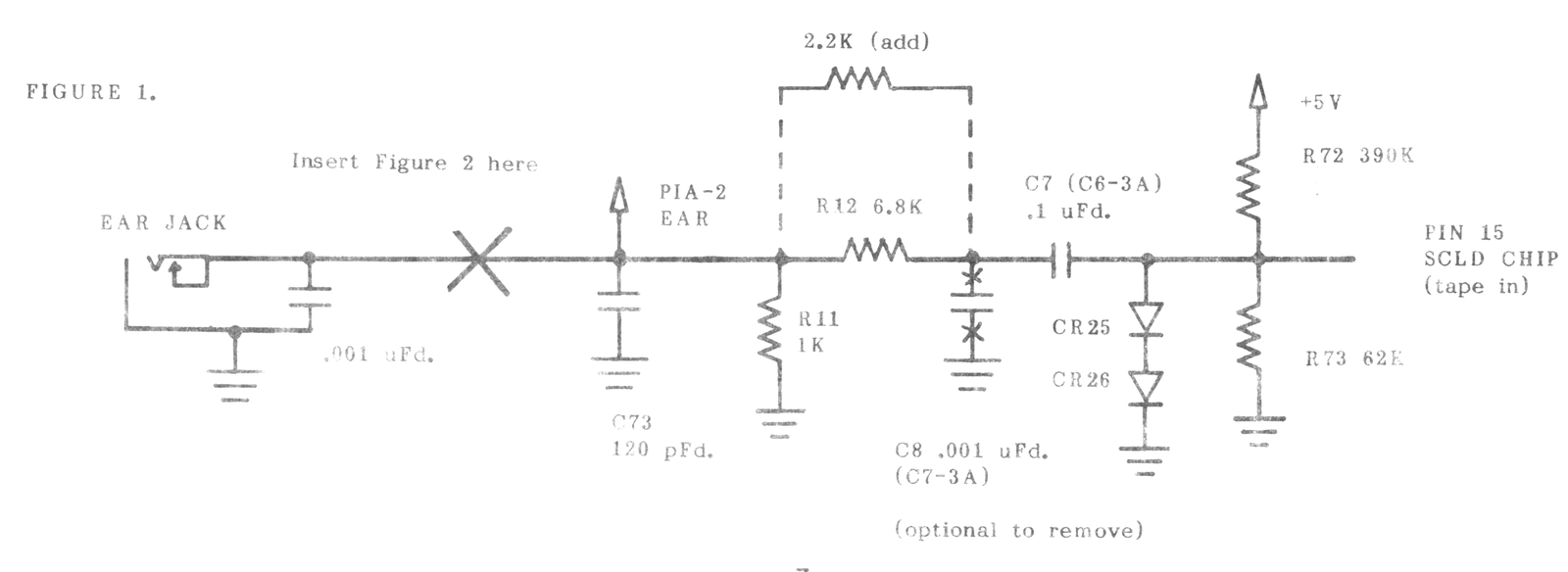
Now, let’s see what we can do to make it easier to “get loaded” on the 2068. The applicable portion of the schematic is reproduced here in Figure 1. As in the case of the MIC jack, there is at least one capacitor (C73) directly across the EAR jack. Again, this (or these) were presumably included to help reduce radio and TV interference. It seems that Timex’s philosophy was, “if some capacitors do some good, then more will do more good.” Unlike the caps across the MIC port, however, the one or ones on the EAR jack have a negligible effect on the tape signal itself. This is because the impedance looking into the MIC input of the recorder is several magnitudes higher (typically about 50,000 ohms) than the impedance of the EAR output (around 10 ohms). As a result, there is nothing to be gained by removing these capacitors, so you might as well leave it in! Who knows, they might even help reduce interference slightly.
Looking further into the schematic, we find a resistor (R11, 1000 ohms) in parallel with the EAR jack as well. Again, this is so much greater than the output impedance of the tape recorder EAR jack that it has no significant effect on the tape signal. It was probably included to provide the DC return required by some recorders. After that is a little network consisting of two resistors R12 and R73, two caps C8 (C7-3A) and C7 (C6-3A), and two diodes (CR25 and CR26). This is essentially a “diode clamp” circuit, which shifts the signal from, say -3 to +3 volts, to about -4 to +1.2 volts. Also, it provides a low-frequency (LF) corner of about 230 Hz., and a high frequency (HF) corner near 23 kHz.
My reason for digging into this was that I sometimes couldn’t get some tapes to load, even at maximum volume setting on my 6 volt TS2020 or Minisette IX’s. A quick measurement showed that my line voltage was somewhat low, around 110 volts. My present home-sweet-home has long secondary power lines and electric heat; I found that some tapes would load ok with the heaters unplugged, but wouldn’t “take” if the AC line voltage dropped below the rated 120 VAC. A colleague reported similar problems, especially when trying to use a fast-load program to speed up the tape processes. If you’re having similar border-line sensitivity problems with tape loading, the following modification may quite possibly handle it.
2068 LOAD Circuit Mods
1: Open the 2068 by removing the seven screws and disconnect the keyboard tail. (Thankfully, the KB tail on the 2068 is considerably more substantial than the ones on the ZX81/TS1000!)
2: Locate the 6800 ohm resistor, R12 (blue-grey-red-gold). This is about 1 cm. below and slightly to the left of the C10 capacitor you removed last issue. Bridge this resistor with a 2200 ohm, 1/4 watt unit (red-red-red-gold). This will make the mod easy to remove if it doesn’t do the trick for you. Alternately, you may clip the 6800 ohm resistor and replace it with an 1800 ohm unit. This increases sensitivity, which in my case was enough to allow loading tapes that wouldn’t quite “take” even at full blast. It also raises the LF corner, making the system yet more immune to low-frequency garbage.
3: I also removed capacitor C8 (C7-3A), even though doing so is not strictly necessary; the HF corner created by this cap is high enough to avoid trouble with the standard tape routines. However, it may conceivably get in the way if you later use VOTEM or other V-F (voltage to frequency) analog interfaces, or if you decide to experiment with fast-load routines. Although the 2068 (about 1500 baud)is a lot faster than the ZX81 (at about 300 baud), a good tape recorder will support even faster loading; up to about 3500 baud, or 440 bytes per second.
4: Reconnect the KB tail, and set the board back into the case. Test your modification. If you’re satisfied that you now have enough sensitivity, screw the two case halves back together.
This will handle many loading problems. Aside from the comparatively low sensitivity of the 2068’s load circuitry, there’s not much for which it can be faulted. Unlike the ZX81, the SCLD custom chip apparently contains a comparator to square up the signil. As a result, adding a comparator or Schmidt-trigger conditioner probably won’t have a noticeable effect. However, if you have a tape recorder with a 6 volt supply, chances are you might still have trouble with sensitivity. If so, here are a few options:
1: You can use VOTEM to help out, but you’ll need to make a couple modifications. First, you’ll have to supply a 9-volt power source such as a “transistor radio” type battery. Then, you’ll have to connect the junction of R1 and R6 to +9V instead of +5, to give you a larger output swing. One caution, however; this modification may make it unusable with the ZX81/TS1000, as these prefer a lower tape signal voltage and some of them balk if it’s too high.
2: Get a recorder with a higher supply voltage, e.g. 7.5 or 9 volt. This will allow a higher output swing.
3: Replace your present 6V AC adaptor with a 7.5 volt unit. These are available from Radio Shack and other sources. Try to get it on the condition that you can return it if it doesn’t do the job. The slightly increased supply voltage will not harm well-designed recorders, but may be just enough to push you “over the hump.” This option, if it works, is a lot cheaper than buying a new deck.
You might experiment with the number of diodes in the clamp. (Be warned! You are dealing directly with the SCLD chip. DON’T BLOW IT!-ed.) This affects the positive clamp level, at the rate of about .6 volts per diode. As mentioned above, the units from GTLB have the two diodes (CR25 and CR26) bridged with a single one. I tried this on mine, and found that it actually seemed to make matters worse. I also tried adding an extra diode in series, and found no noticeable change. You might also try increasing C8 (C7-3A) to, say 0.22 uF., especially if you reduced R12.
PARTS LIST - 2068 LOAD AMP

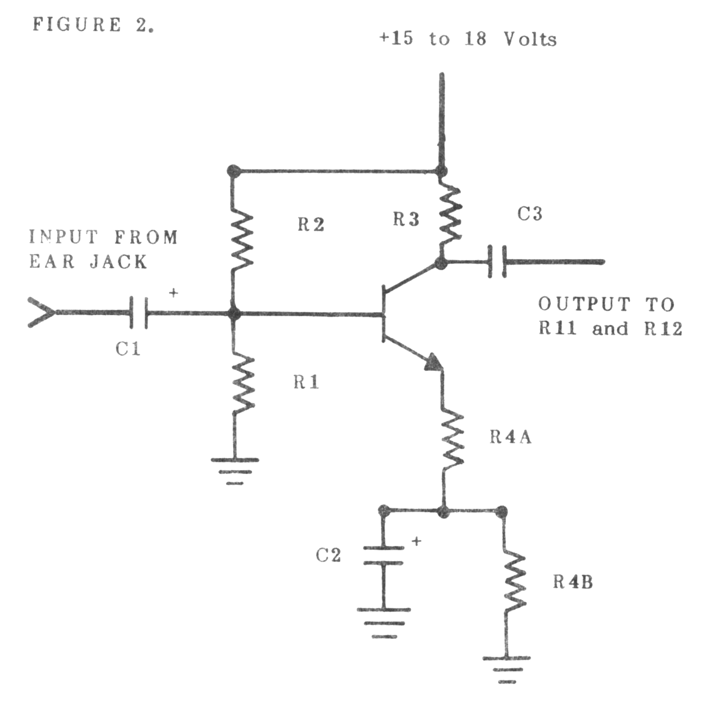
C1-C3 - 1uFd., 16V tantalum
C2 - 47 uFd., 6V electrolytic
Q1 - general purpose audio transistor
     2N3904, 2N4401, etc.
R1 - 910 Ohm 1/4 watt
R2 - 4700 Ohm, 1/4 watt
R3 - 470 Ohm, 1/4 watt
R4A - 100 Ohm, 1/4 watt
R4B - 33 Ohm, 1/4 watt

1"x 1" perfboard, wire, solder, sticky foam.
** For the convenience of those readers who would rather not scout around for parts, I (Fred Nachbaur) will wire up these boards, so that they will be ready for you to install, for $6.00 each (add $3.00 for speedy mail service). You’ll then only have to cut one trace and make four wire connections.
The Final Solution
If you reduced the value of R12 as described above and still don’t get enough sensitivity with your deck, and if the other “fixes” don’t appeal to you, your best bet is to add a linear amplifier to boost the signal to the computer. Not much gain is needed, so a single-transistor “class A” stage is all you need. The circuit of Figure 2 is the answer that my ZX81 “CE AMP” program came up with. It has a voltage gain of about 3, and a P-P output swing of about 10 volts. Cost in parts is around $4, depending on how much of the circuit you have in your junk box. On my machine, it allows most tapes to load reliably with a volume setting anywhere between 4 and 10.
Wire it up on a 1″x1″ piece of perf board, cut the trace to the EAR jack (underside of board) and connect the EAR jack to the input. Connect the output to the left side of R12. Get the +15 volts power for the circuit from the on-off switch (SW2), the leg closest to the front edge of the board. A good place to get the ground is from the grounding strap soldered to the top of the video-section enclosure. (If you want to get fancy, you can make use of the expansion port area. A1-top left is ground, A2 is the EAR jack and B3 is the +15V power.-ed.) The transistor can be virtually any NPN silicon type capable of at least 200 mW. dissipation and having a current gain (beta) of 50 or higher; e.g. 2N3904, 2N4401, etc. (Beware of the Radio Shack “2N3904 grab-bag.” These are, in my experience, pretty lousy.)
Mount the board on top of the keyboard diodes (in front of the keyboard connector) using sticky-foam; watch for shorts. If you wish to use one of the little “Walkman”-type recorders with their 3V supplies, increase the gain to about 4 by making R1 = 1000 ohms, R4A = 75 ohms, R4B = 62 ohms. C1 and C3 should be 16V tantalum units, C2 may be an aluminum electrolytic rated 3V or up.
Load Amp for TS1000
You can use the one-transistor load amplifier circuit with the ZX81/TS1000/TS1500 by making the following changes in component values: *
R1 = 1000 ohms     R4B - not used
R2 = 4700 ohms     C1 = 1 uF.
R3 = 160 ohms      C2 - not used
R4A = 33 ohms      C3 = 3.3 uF.
* As for the 2068, pre-wired boards are available from the author for $6
These changes are necessary because of the different supply voltage (9V instead of 15V) and input resistor value (220 ohms instead of 1000 ohms) as compared to the TS2068. Gain is set at about 3, and P-P voltage swing is just under 5 volts.
If you’re using fast-load routines such as Z-XLR8, SDS, or Q-SAVE, it is recommended that you change capacitor C11 (located near the MIC jack on the ZX81 board) from 47 nF. to 20-22 nF (.02-.022 uF.). This increases the HF corner of the SAVE circuitry from about 3.5 kHz. to over 7 kHz. and provides a brighter signal. I did this simply by breaking the existing capacitor in half horizontally, using a pair of wire nips; works fine, but not a “guaranteed” procedure. After doing this mod, I found that I could run SDS (similar to Z-XLR8 at top speed) even without a pre-conditioner.
So there you have it. That should wrap it up, at least from a hardware standpoint. In a future issue we’ll try to get you a flexible, variable fast-load routine. ‘Till then, “good loads, fair weather!”