
Ed.—A WORD OF CAUTION: Any hardware project that involves modifications to your computer must be approached with extreme caution. SYNC cannot be responsible for problems that may arise from attempting hardware projects. Obviously, any damage done to the computer can be costly in time and money for repairs or even replacement.
I was very pleased with the new Basic that my ZX80 ran after I installed the new 8K ROM. The command set was much closer to “normal” Basic and all commands were available as single keystrokes. This was a considerable improvement over the 4K ROM.
However, as soon as I was finished testing the new features of this ROM, I was very disappointed to discover that my old 4K programs were not directly compatible with the new 8K system. In the first place, the tape standards were completely different, so that all programs would have to be entered from the keyboard. Secondly, not all commands were directly transferable so that in several cases I would have to edit and debug programs that already ran on the 4K system. Worst of all, the machine language programs that I had purchased were worthless since I could not simply enter them through the keyboard. I felt that I had to have the option of using either the 4K or the 8K ROM on the same ZX80.
My first idea was simple—install the appropriate ROM as needed: use the 8K for all new programming efforts, and the 4K for any old programs I might run. After taking the computer apart several times to get at the ROMs, and bending more than a few pins, I knew that idea was too simple.
This article describes the final solution that I used to make both ROMs available to my ZX80. I installed the ROMs piggyback in the socket and switch selected the ROM to be used. The modification is very simple and requires only a soldering iron, an spdt switch, and a few inches of wire.
The completed 4K/8K piggyback ROM assembly is shown in Figure 1. The first step to making the assembly was to remove the ROM from the ZX80. Pin 28 on each ROM was bent up slightly so that it was at a 45 degree angle to the other pins. (Pin 28, incidentally, is the pin to the right of the notch in the top of the ROMs.) This is the power pin of the ROMs; if power is not applied to the ROM, the rest of the system does not know it is in the circuit—even if all other pins are connected. By switching the power to only one of these pins only one ROM will be active at any time.
Except for pins 28, all of the other pins of the ROMs were connected in pairs by soldering them together. This was done by placing one ROM on top of the other (piggyback) with the notches at the same end. Each pin on the top ROM just overlapped the corresponding pin on the lower ROM by about one-tenth of an inch, and the only contact was between pairs of pins. It makes no difference which ROM is on the top, but I put the 8K one there.
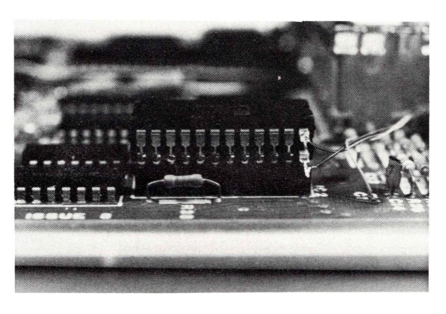
The next step was the hardest one—the pairs of pins were soldered together. Each pair of pins was carefully heated with a soldering iron and a small amount of solder was applied where the pins overlapped. The solder was applied carefully so that no solder bridges were made between adjacent pairs of pins. Care was also taken to avoid getting solder on the tips of the pins of the lower ROM since they would be inserted in the socket of the ZX80. The bent pins (pins 28) were not soldered together.
A five inch piece of wire was soldered to the tip of each bent pin 28. The pin and wires were carefully oriented so that they did not touch each other. The wire from one of the bent pins was attached to each of the switched terminals of the spdt switch. A third five inch piece of wire was soldered to the common terminal of the switch. The wires were twisted together to keep them from tangling too much.
The piggyback ROM assembly was installed in the ROM socket of the ZX80. The bent pin pair was not inserted in the socket. The free end of the wire attached to the common terminal of the switch was soldered to +5V at the trace that leads away from pin 28 of the ROM socket. This trace can be seen to the right and above the ROM socket in Figure 1. The switch was mounted at a convenient location on the right edge of the case, and the case was reassembled. I found the greater height of the ROM assembly caused a slight gap in the ZX80 case, but I did not feel it was bad enough to warrant removing the socket and soldering the ROMs in place.
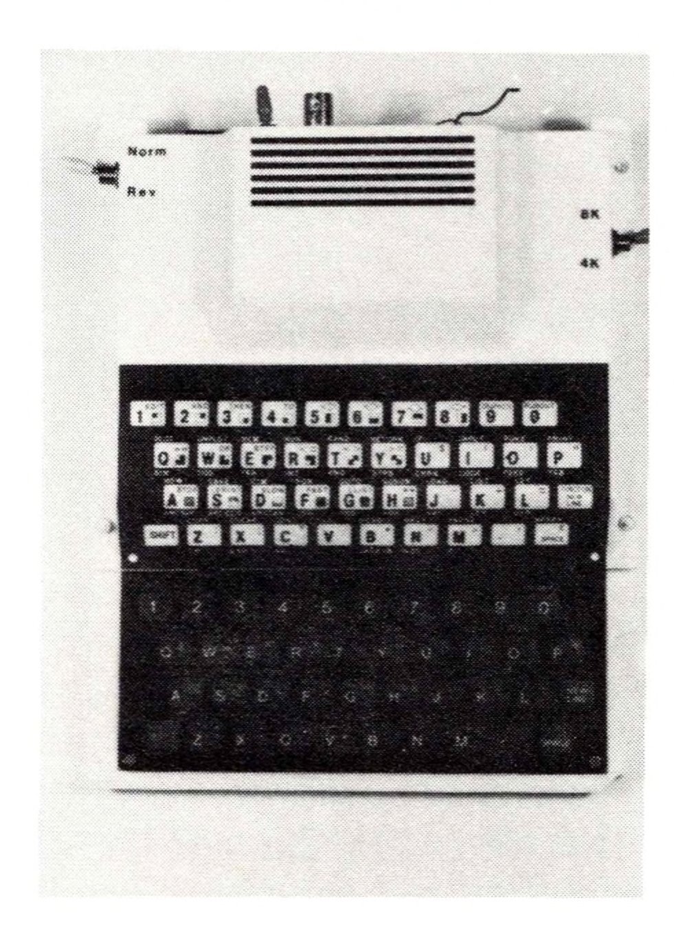
The combined 4K/8K ROM was easy to test. I applied power to the ZX80 and typed a zero. The 8K ROM displays a zero with a slash through it while the 4K ROM zero has no slash. I made sure that each switch position selected one of the ROMs and labelled the switch. The final step in the assembly was to put the 8K keyboard overlay above the original keyboard (as shown in Figure 2) so that I could refer to the appropriate key legends for each ROM.
I now have a much more flexible ZX80 than is available with just one ROM. None of the 4K programs in which I invested either time or money will be wasted, and yet I am able to use any new 8K program that I might obtain. I also never have to worry whether a program I find published in SYNC will be compatible because I have both ROMs available at a flip of a switch.