
After obtaining your joystick, you will notice that it has 5 functions: up, down, left, right, and a “firing button”. Next, notice that there are 6 wires coming from the unit of which one wire will be the common wire. The others will be connected inside to each of the functions. You must then check by continuity, which wires are operated by which function and determine the common wire. For example, the white wire may be the common wire and the blue and white wire make up the “up” function. Determine what they are and keep a written record of each wire.
In order to plug and unplug the joystick from your computer, you will need a 6 connector male and female plug which can be obtained from Radio Shack. These plugs will have numbers stamped on them from 1 to 6. Mark these down with the corresponding wire colours. (Of course, any number can be assigned to any colour). Thus far, you should have written down something similar to this:
white - common - 1 (plug connection)
blue  - down   - 2
etc.
Solder the wires to the male plug. Also note that the plug only fits the female plug one way so that after completion, you should not be able to connect the plugs the wrong way.
Next, wires must be soldered to the female plug in the same way. If different coloured coded wires are used for the female end, you must make a notation of this beside the above notations: e.g.
Male                  Female
white - common - 1 - red
etc.
If you happen to using the same colour wires for the female end then you will have to mark each individual wire with masking tape with the male colours written on it.
If a keyboard has been added, then you can solder the wires from the female end to the keyboard or you will have to go inside the computer.
If you have previously wired the keyboard, then you will understand the following instructions. If you have not, see the detailed instructions in “The Explorers Guide to the ZX81“, page 107.
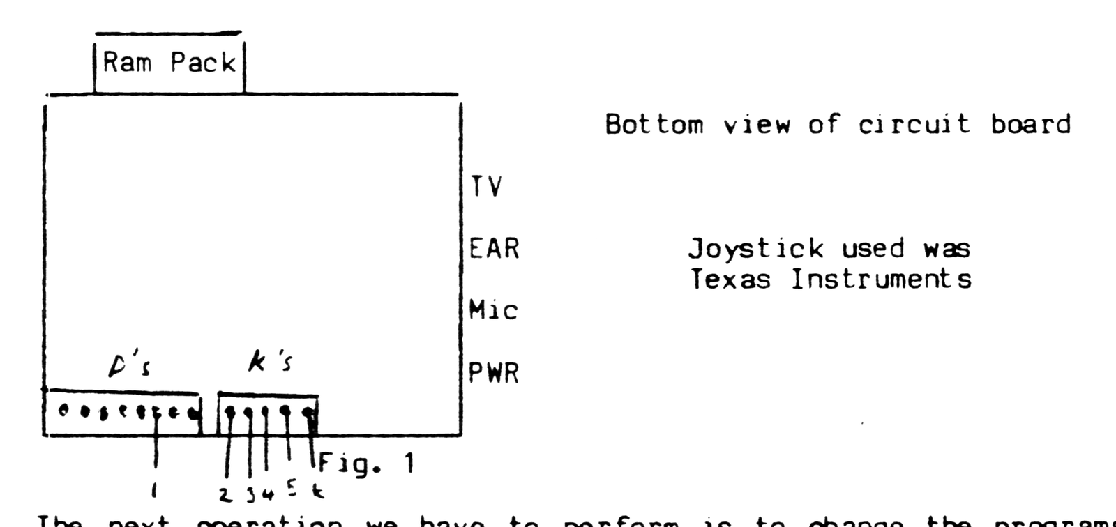
Once the computer is opened up, you should see where the wire ribbon comes from the keyboard and is attached to two small black plugs. On the underside of the printed circuit board is where you will make your soldering connections. See fig.1 for soldering instructions.
After soldering the 6 wires in, ensure that you have not de-soldered any of the diodes or resistors from the ZX curcuit board
Now plug in the computer and begin to test the joystick. As we are testing it, you will notice that the joystick works on 2 different keys than we normally would use in a program; namely the 9 and the 0. The reason is that there is only 1 common wire to all functions and keys 6,7,8,9, and 0 use this common wire. At the end of the article is another way to wire it using the regular keys. Back to testing. Push the joystick up–the computer should read on the TV – 7; left – 9; right – 8; down – 6; fire button – 0. If nothing works or you are getting the wrong printout then check your soldering connections. Check also that you didn’t put on too much solder and short 2 wires together.
The next operation we have to perform is to change the programs to enable us to use the joysticks. Anywhere in the program where it makes mention of “INKEYS 5” we must change it to INKEY$ 9. (or it may be the code of inkey which has to be changed). Also, if F or some other key was used, then it has to be changed to INKEY$ 0 or the CODE number of zero. At this time I cannot give you any information to change a machine code routine to conform with the above connections.
The following is an alternative to wiring the 5 (arrow) key and the F (firing key). Since they are both on different circuits within the computer, you will have to open up the joystick and disconnect the common side of the left movement and the common side of the “firing button”. To make these connections on the circuit board of the computer see “The Explorers Guide”.