
Editor: Those readers following along with Syd’s Machine Code series, should note that there were two textual errors in the Nov/Dec ’86 issue, that need to be corrected. Last paragraph, first column on page 19 should read, “the status of these bits is unimportant.” The last sentence of the fourth paragraph on page 20 should read, “the only flags affected are the P/V and zero flags. The P/V flag is reset if BC=0. The zero flag is set to indicate a match, just as in a normal CP instruction.”
This lesson we will discuss the stack and the instructions which use the stack. What is a stack? A stack is simply an area of consecutive bytes of memory which are used for storage by the CPU. The CPU cannot operate without a stack. We will find that we too can use the stack, if we are careful.
Remember our earlier discussion of ROM, RAM and boxes? If not, you need some back issues! Think of our CPU’s stack as a stack of boxes (memory locations). You can remove or add to the top of the stack easily, but try to remove or add a box somewhere in the middle and the stack topples. CPU’s stack works the same way except it grows down from the top as if the boxes were suspended from the ceiling. Therefore, we actually add to the bottom of the stack.
There is a special register inside CPU dedicated to keeping track of the stack. Its mnemonic is SP which means Stack Pointer. SP contains the address of the last location on the stack.
All information on the stack is stored in the usual two byte format used for addresses. We can place information on the stack (PUSH) or remove it from the stack (POP). Our friend CPU automatically adjusts the SP with each operation by the required two bytes. It is important to realize that even though SP is adjusted to point to the correct location (box), the information is still there until it is overwritten. See Fig.1 to make this clearer.
The PUSH and POP instructions can add/remove information to/from the stack and any register pair. For instance, if we wish to stack the contents of the B register, we need to PUSH BC. We will have also stacked the C register, since we must use a register pair.
Last issue we learned the CALL instruction. It uses the stack to save the value of PC in order to know where to return to. In effect, CALL executes a PUSH PC, JP to new location and complete the subroutine, and then a POP PC (Ret) and continue executing the program from the byte after the CALL instruction.
The next instruction is Ld SP,HL. This is a simple assignment instruction. Whatever value held in HL will be copied into SP, not the stack. Remember, most instructions assume all values on the stack to be valid addresses, even if they are data, so it is important to know where SP is.
The last instruction affecting the stack is EX (SP),HL. It will exchange the contents of the address referenced by the SP with the value held in HL. Assume HL + 1040h and SP = 9050h and address 9050h = 59 and address 9051h = 68. After the EX (SP),HL instruction is executed, their new values will be; HL = 6859h, SP = 9050h, address 9050h = 40h and address 9051h = 10h. Notice that SP is unaffected. However, the contents of the last stack entry are changed.
This is a good time to introduce the other exchange instructions. They are all fairly easily understood and are listed in the chart. Note that an exchange merely swaps the contents of the affected registers and no others, neither are any flags affected, except for the EX AF,AF’ instruction. The EX AF,AF’ exchanges only these registers while the more general EXX exchanges BC, DE & HL with BC’, DE’ & HL’.
These exchange instructions do not actually change the register contents. Consider the EX AF,AF’ instruction. The AF register becomes the AF’ register and the previous AF’ register pair becomes the new AF register pair. This is important as the contents of registers can be stored out of the way for later retrieval. It also means we must be sure of which set of registers are in use.
The EX DE,HL instruction is very useful and will exchange the contents of DE with the contents of HL. This is the same as if there had been an instruction to Ld DE,HL and Ld HL,DE without disturbing any of the values. A series of PUSHes and POPs would be needed to accomplish the same result. For example, lets EX BC,HL (there is no such instruction):
PUSH BC
PUSH HL
POP BC
POP HL
Figure 1
  Stack
+---------+
!   80    !       Assume the top two locations of the stack
!---------!       contain the address 8000h, that the SP is
!   00    !  SP   set at 61FEh and HL contains 0C40h. A Push
!---------!       HL instruction will load 0C40 in the next
!   0C    !       two stack locations, 61FDh and 61FCh, and
!---------!       Dec SP twice, thereby making SP = 61FCh.
!   40    !       A subsequent Pop HL instruction will then
!---------!       Inc SP twice while placing 0C40h into HL.
!         !       It is important that even though SP has
!---------!       been adjusted, locations 61FCh and 61FDh
!         !       still contain the address 0C40h and will
!---------!       until it is overwritten by another stack
                  operation.
Chart 1
Stack               Exchange
Push rr           ! Ex AF,AF'
Pop rr            ! Exx
Ld SP,HL          ! Ex DE,HL
Ld SP,nn          ! Ex (SP),HL
Ld SP,(nn)        !
Inc SP            !
Dec SP            !
Note that the information was moved from the stack into a different register pair than it originated from. This is a very useful tool to have at our disposal. However, we must be aware of what we are doing or we may find ourselves expecting data at a location other than where it ended up.
You will no doubt have noticed that I have rater laboriously explained the many instructions we have learned up to this point. The truth of the matter is that I have been trying to walk the fine line of too much detail/not enough detail. I hope there has been enough to get you started without boring anyone.
We now have enough instructions to begin programming. I firmly believe the only way to learn any language is to use it. With that in mind, we will concentrate more on accomplishing some task and less on the instructions. I must assume that if you are still with me, you have by now acquired some good books to supplement your learning.
We will need to be able to “see” if our programs are completing the task as we desire, therefore, we will initially write programs that will affect the display file. This will necessitate two separate discussions, as the TS1000 and TS2068 each handle their display files differently. You may wish to skip the section which does not pertain to your computer, but I think you will find it beneficial to read.
Before we jump right into it though, we need to look at the Sinclair manual again. Towards the back of the manual you will find a section on the system variables. These are variables used by the Basic operating system to keep track of various items. Many of these will prove useful to us and several others are required to be under our full control. I will use Sinclair’s names and explain each one as we need it. You should take a moment to review this section of the manual as we will become comfortable with many of the system variables.
Timex Sinclair 1000
The display file (D-File) is arranged as 24 rows of 33 characters. The last character in each row is an end-of-line (EOL) marker, which is CHR$ 118 (the code for Enter). In addition the very first character is an EOL marker. We must never ever overwrite any of the EOL markers. If we overwrite any of the EOL markers, the system will crash!
This description only applies to a fully expanded system (greater than 3.25k). The D-File is collapsed to 25 EOL markers in a smaller system. I will assume yours is fully expanded.
Since the D-File moves about in memory as your Basic program expands and contracts, its location is held in a system variable known as none other than D-File. This means that we can always locate the D-File with the instruction Ld HL,(D-File).
The easiest way to print to the D-File is to use the RST 10h instruction as that is where Sinclair has placed the print routine. RST 10h will print whatever character is in the A register. Enter the following to get a full screen of asterisks:
Listing 1
0E16      Start  Ld C,18h          ;line counter
0620      Loop1  Ld B,20h          ;characters/line counter
3E17      Loop2  Ld A,17h          ;character to print
D7               Rst 10h           ;go print it
10FB             DJNZ,Loop2        ;until line is full
0D               Dec C             ;count one line done
20F6             Jr NZ,Loop1       ;another line?
C9        Done   Ret               ;return to basic
While RST 10 is the easy way, it is only a minor improvement over Basic. That’s because we are using the same routine as Basic uses. The advantage is that we didn’t have to keep track of the EOL markers.
The fastest way to print to the screen is by direct pokes, even from Basic. Enter the following for an almost instant screen fill:
Listing 2
2A0C40    Start  Ld HL,(D-File)    ;get D-File location
0E18             Ld C,18h          ;line counter
23        Loop1  Inc HL            ;get past EOL
0620             Ld B,20h          ;characters/line counter
3617      Loop2  Ld (HL),17h       ;poke character onto screen
23               Inc HL            ;advance print position
10FB             DJNZ,Loop2        ;go do again?
0D               Dec C             ;count one line done
20F5             Jr NZ,Loop1       ;do another line?
C9        Done   Ret               ;return to Basic
You should have noticed that this method allowed printing on all lines. There is a system variable, DF_SZ, which can be poked from MC or Basic to allow full screen printing, however, the system can be easily crashed if not properly handled. Also, the number 17h can be any printable character code.
Now for an all purpose, generic print routine:
Listing 3
1A        Print  Ld A,(DE)         ;check for EOL marker
FE76             Cp 76h
2001             Jr NZ,NoEOL
13               Inc DE            ;get past EOL marker
7E        NoEOL  Ld A,(HL)         ;get character to print
FEFF             Cp FFh            ;check for end of text
C8        Exit   Ret Z             ;and return if reached
12               Ld (DE),A         ;print it
23               Inc HL            ;advance character pointer
13               Inc DE            ;advance print position
18F3             Jr Print          ;do it again
The print routine is useless by itself. Upon entry, HL must contain the address of the first character to print and DE must contain the address in the D-File to print at. Enter the following routine to understand how you would set-up HL & DE and Call this routine at Print.
Listing 4
2A0C40    Entry  Ld HL,(D-File)    ;get D-File location
EB               EX DE,HL          ;into DE
210041           Ld HL,Text        ;get address of text
                                   ;address assumed to be 4100h
CD8240           Call Print        ;go print message
                                   ;address assumed to be 4082h
C9        Done   Ret               ;return to basic
And now a message must be stored at 4100h. Enter these hex codes to address 4100h:
Hex Dump 1
39 2D 2E 38 00 2E 38 00 26 00 39 2A 38 39 1B
00 2E 00 38 3A 37 2A 00 2D 34 35 2A 00 2E 39
00 00 3C 34 37 30 38 1B FF
Note that the print routine requires a terminating byte FFh in order to exit. Our test should now work with the command Rand Usr Entry.
Timex Sinclair 2068
The D-File consists of 192 lines of 32 bytes/line for the character information and 24 lines of 32 bytes/line for the attribute information. The last 768 bytes are known as the Attribute File (A-File). The D-File is fixed in memory at address 4000h and the A-File resides at 5800h. We will discuss the A-File at another time, as its purpose is to hold the color attributes of each character square. We will therefore not be using the A-File at this time.
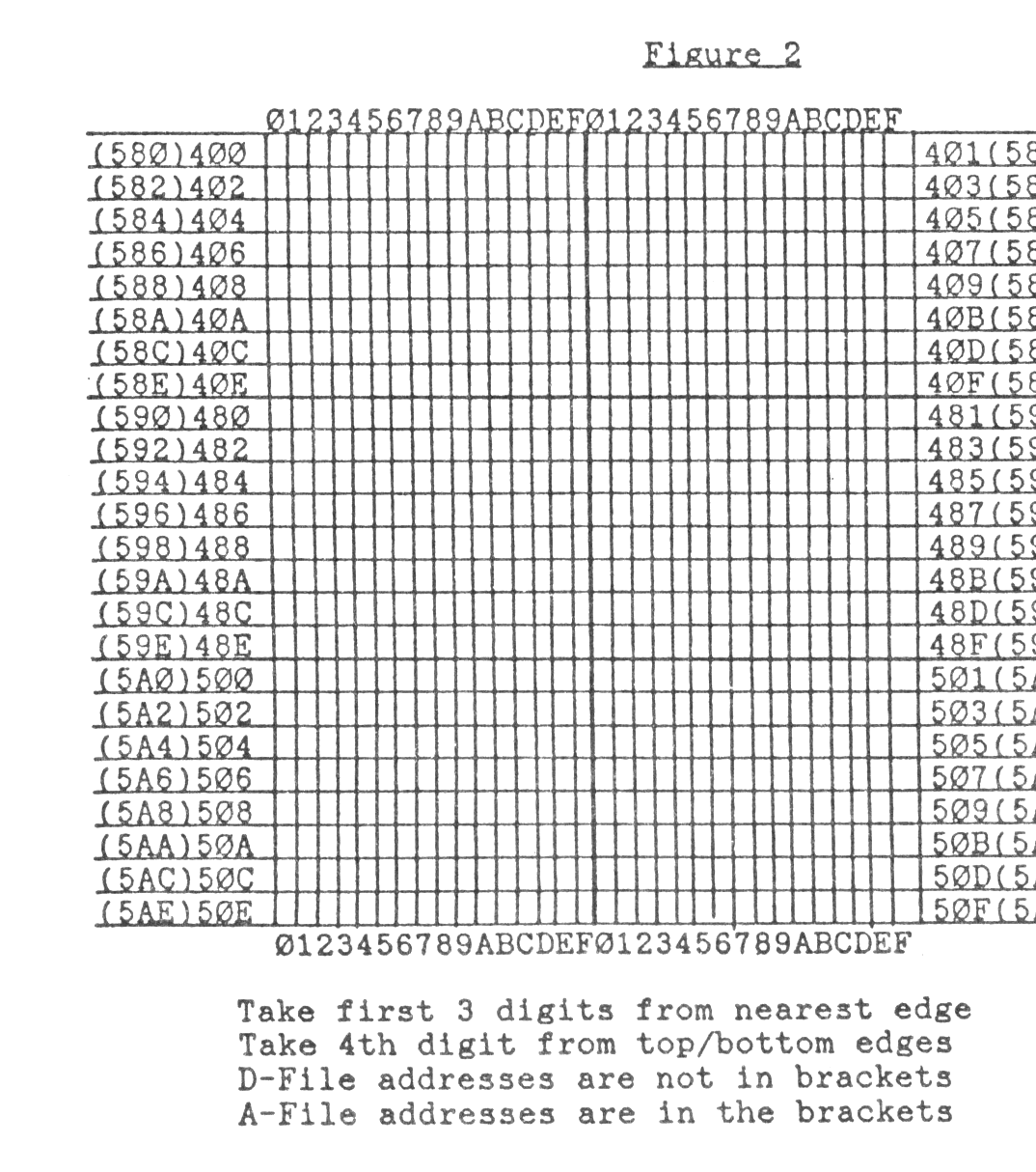
The organization of the D-File is not what you would expect. Each character is eight pixels by eight pixels (one character square). The eight pixels across fit nicely in one byte, hence the 32 bytes across each line. The problem is the eight bytes needed to make each character are not stored consecutively. Looking at Fig.2, you can see that the D-File is split in three sections of 64 lines each. Within each section, the eight lines which comprise each character are 256 bytes apart (8 lines * 32 character spaces). The junction of two sections is where there is a difference as the sequence begins to repeat. Study Fig.1 to make this clear. I am told this unique structure has something to do with the way in which a TV draws its scan lines. Since I understand very little about the hardware, I must claim ignorance and accept this explanation.
This means that the easiest way to print to the screen is by using RST 10h, which is where Sinclair chose to start an all purpose print routine. Once again though, things are not as easy as they would seem. The 2068 uses channels and streams to direct the traffic (we will discuss channels and streams later). This means that we must be sure we know where we are directing the output of RST 10h or else we will have no idea where it will end up.
Do not allow the D-File structure to put you off. We can still write to it if we understand its structure. Also, many of the routines we will need to help us handle it, are already located in the ROM.
Let’s try a simple print using RST 10h. Enter Listing 1 from the TS1000 area above and run it with Rand Usr address.
You should get Error 5 on running this one. Notice how the bottom line is printed and scrolled. Probably not what you expected. We could call the channel open routine to fix this, but there is an upper/lower screen flag that can be temporarily set. If we reset bit 0 of TVFlag, we can print to the upper screen. Insert as the first two instructions:
213C5C           Ld HL,TVFlag      ;get TVFlag address
3600             Ld (HL),00        ;reset flag
Now run the routine. Works great! A much better way is to only affect the bit needed. This requires the instruction Res 0,(IY+02), which we have not learned yet. You could also have achieved the same result with the first routine if you ran it with Print Usr address. This sometimes leads to undesireable results, therefore, we will always use Rand Usr address or Let x= Usr address.
Lets attempt to poke a character directly onto the screen. It cannot be done in one easy step as was the case with the TS1000. We must now resort to a complicated routine such as:
Listing 5
C630      MakeC  Add A,30h         ;offset to make number
                                   ;a printable character
ED4B365C  Print  Ld BC,(chars)     ;find character table
E5               Push HL           ;save character location
2600             Ld H,00h          ;transfer character
6F               Ld L,A            ;to HL
29               Add HL,HL         ;multiply by 8
29               Add HL,HL
29               Add HL,HL
09               Add HL,BC         ;get offset to character
                                   ;data in table
EB               EX DE,HL          ;address of data to DE
2AB05C           Ld HL,(Store)     ;we are storing address
                                   ;in D-File to print at
                                   ;in store
0608             Ld B,08h          ;# of lines/character
1A        Loop   Ld A,(DE)         ;get pixel data
77               Ld (HL),A         ;poke it to D-File
24               Inc H             ;adjust print pointer
13               Inc DE            ;adjust data pointer
10FA             DJNZ Loop         ;are we done? loop back
                                   ;if not, to complete
21B05C           Ld HL,Store       ;get and adjust print
34               Inc (HL)          ;position
E1               Pop HL            ;retrieve char location
C9        Done   Ret               ;one character printed
This routine is worthless without some data to print and another routine to set-up the registers and call it. Notice that there are two entry points. Print is the normal entry, however, MakeC is used to print a number without having its character code (as in raw data, instead of text). The unused location of 5CB0h in the system variables area stores the address of the next print position.
Upon entry to Print, we need to have the character to be printed in A. The HL register points to the character to print and needs to be preserved while Print is executing. Also, note that the program expects the data string to end with a byte containing FFh. Enter the following routine to set-up the registers and Call Print for a test. Your command to execute is Rand Usr Entry.
Listing 6
210040    Entry  Ld HL,4000h       ;1st address to print
22B05C           Ld (Store),HL     ;at into our variable
213075           Ld HL,Data        ;data string address
                                   ;assumed to be 7530h
7E        Loop   Ld A,(HL)         ;get character
FEFF             CP FFh            ;is it the end of
                                   ;string yet?
C8        Exit   Ret Z             ;ret if so
CD0080           Call Print        ;else go print it
                                   ;Print assumed to be
                                   ;at 8000h
23               Inc HL            ;advance char pointer
18F6             Jr Loop           ;get next character
And here is the data as a hex dump:
Hex Dump 2
54 68 69 73 20 72 6F 75 74 69 6E 65 20 77 69 6C
6C 20 6F 6E 6C 79 20 70 72 69 6E 74 20 69 6E 20
6F 6E 65 20 74 68 69 72 64 20 6F 66 20 74 68 65
20 73 63 72 65 65 6E 20 61 74 20 61 6E 79 20 20
74 69 6D 65 2E FF
Be sure you have used the same addresses or change them to suit. If any address is not correct, you may crash.
Well, that’s all folks, See ya next time.