The circuit described in the February 1986 issue of SUM was designed around the Sears RGB/TV/Monitor (same as the Sanyo model # 31C426) and the Magnavox (NAP) RGB-40 or 80.
Both of these monitors (and the QL monitor as well) take negative-going composite sync and active high RGB signals and have well buffered inputs to clean up any poor inputs.
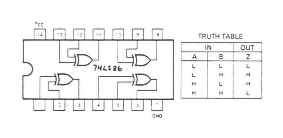
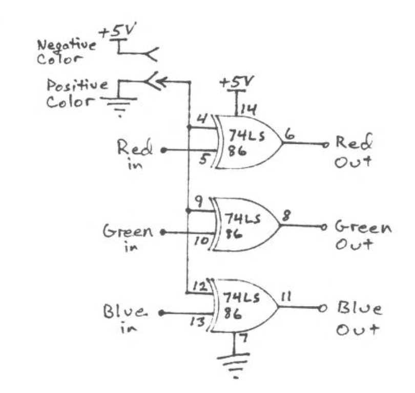
Many RGB monitors out on the market don’t have these features and therefore do not work very well or at all with the circuit described. With the simple addition of a 74LS86 Quad 2-input Exclusive OR gate, you can shape (buffer) and invert all four signals to what ever format you need by changing the polarity of one of the two input lines on each of the four gates.
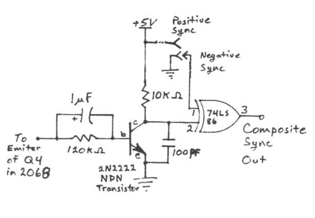
Also, I neglected to say what transistor was used in the original circuit; it is a 2N2222, Radio Shack #2762009. Although, any garden variety NPN transistor should work.