Authors
Publication
Pub Details
Date
Pages
This project is the first in a series of articles which will chronicle my ongoing experiments in the development of a low-cost completely computerized weather station making use of TS computers, the Experimenter’s Universal Input/Output Port, and a collection of common household items.
I think you will enjoy following my trials and tribulations. After completing this first part, it is apparent that there shall be some very interesting computer concepts covered here which will be applicable in many different situations. If you decide that you’d like to try building some of the projects yourself, welcome aboard. Please tell us about your ideas, experiments, findings, failures and successes. Bear in mind that above all else, I am a tinkerer; not an engineer or electronics wizard. So please, all you engineers and electronics wizards out there, be forgiving when you see my designs. Help out if you can by sharing your thoughts.
An anemometer is a device which tells you how fast the wind is blowing. Usually, anemometers work by having some sort of arm stuck up in the wind. The wind spins the arm which is connected to the shaft of a generator. The harder the wind blows, the faster the arm spins. The generator will produce higher voltage. By measuring the volts, you can calculate the windspeed.
The anemometer I built operates on roughly the same principal, except instead of generating a voltage, the spinning arms of the rotor slice through a light beam. The computer is interfaced to the anemometer through a light detector so what the computer sees is a series of high and low pulses as the arms break the light beam. As windspeed increases, and the anemometer spins faster, it is not a higher voltage which is produced but a higher rate of pulses per unit of time. In other words: a higher FREQUENCY. By measuring the frequency, the computer can calculate the windspeed.

Construction of the Mechanical Parts
Look at figure | to get an idea of how the anemometer is constructed. A ping pong ball which has been cut in half is used as the wind collectors. When you cut the ping pong balls, use a SHARP utility knife. After the initial cut, trim the halves with scissors until each is exactly the same size.
Once you’re finished with the ping pong balls, set them aside and build the shaft assembly. First, take a small mending plate (or similar metal bar 3 inches long by 1/2 inch wide) and mark its center point. Cut a piece of 1/4 inch copper tubing about an inch and a half long. Ream any burrs that formed on the inside of the tube as a result of the cutting process. Make sure that the ends of the tube are straight and square. Run the ends across a grind stone or file them if necessary. A 16 penny common nail should freely pass through the tube. Now use super glue to stick one end of the tubing to the mending plate. You should be able to look inside the tube and see the center mark of the mending plate in the exact center of the tube. Go slow and get it right!
Use vice grips or pliers to squeeze the head of the 16 penny nail into the end of a wooden mast. This will allow the nail to stick up straight. Wrap electricians tape tightly around the nail and mast to secure.
Place the tube and mending plate rotor over the nail. The rotor should spin with very little drag. Mix up some epoxy and glue the ping pong ball halves onto the ends of the mending plate. Don’t forget to face them in the right direction, and take pains to insure that the cups are spaced equally from the center. While you’re at it, gob a generous amount of epoxy in the area where the tubing connects to the mending plate. Spread the epoxy right around the tube and over the top face of the mending plate. A lot of stress will build up here in a high wind.
As in all rotating objects it is important to try to keep the rotor properly balanced. That is why you should be careful in your positioning of the tubing and the ping pong balls. Before you clean up the epoxy, try spinning the rotor gently. If you see it wobble and shimmy, place a bit more epoxy on the mending plate to bring it into balance.

Electronics Construction
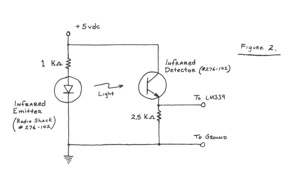
While you’re waiting for the epoxy to harden, begin work on the electronic portions of the anemometer. As mentioned previously, a light emitter and detector circuit must be located at the rotor. It must be positioned so that the light path between the two will be broken by the mending plate as it spins. Use the schematic diagram and the drawing shown in figure 2 as a guide in fabricating the circuit on a small piece of perfboard. Use about 6 inches of lead wire soldered to both the infrared emitter and detector.
After all connections are soldered, cover the board completely with electrician’s tape to protect it from the weather. Then tape it to the wooden mast as shown in figure 1.
Cut up a coat hanger and form it in a shape similar to that shown in figure 1. Use a wood screw to fasten it to the end of the mast. You want to bend the coat hanger so that it will hold the emitter and detector about an inch apart, and at the same time allow the cups of the rotor to spin freely. Use more electrician’s tape to secure the emitter and detector as well as the lead wires to the coat hanger wire. Be sure the emitter is lined up so its light can be seen by the detector.

If you wired the circuit up properly, you should have three leads coming down off the mast. They go into your computer room. The +5vdc and ground lines can connect directly to your computer. I did this by soldering two wires to the power pins on the underside of the I/O port edge connector. If you turn the port upside down, the +5 volt line is on the extreme right side. The ground is the fat trace immediately to the left of the key slot. The third line coming from the mast is the data line which must be fed to the input of an LM339 quad comparator chip which is shown in figure 3.
The comparator chip functions as a “level detector”. It compares the voltage coming from the light detector (at pin 5) with a reference voltage (at pin 4) which can be adjusted by turning the 100 Kohm variable resistor shown in the schematic. Whenever the voltage from the light detector is greater than the reference voltage, a high signal is output to pin 2. When the voltage from the detector is less than the reference, pin 2 goes low.
The comparator is essential for cleaning up spikes and glitches coming in from the light detector. The adjustable reference voltage takes into account different voltage drops which occur when you set the anemometer up at various distances. The comparator’s output is a nice sharp 0 to 5 volts–just perfect for sending into the computer via the input port.
Build the comparator circuit on a piece of perfboard or a solderless breadboard. Supply it with 5 volts from the computer. Every data sheet on the LM339 I’ve read says that you must ground all pins of the chip which are not used. While this may very well be a good practice, I have found that doing this has no effect on the circuit. So for convenience and simplification, don’t bother grounding the pins. Besides, we may want to use the 3 unused comparators in the LM339 for something else later.

Testing the Anemometer
Before you permanently install the (+) anemometer, you will want to test it inside. With my rig, I used a four foot long mast. It was held in a vice on the floor. A fan was directed at the cups on the mending plate. The fan gave it a nice slow spin of about 1 revolution per second. In your tests, you will find that it is much easier to see what’s going on if you keep the anemometer from spinning too fast. For now, the slower it spins, the better.
Hook up wires to the +5 volt and ground lines of the port board as previously described.
Plug the port into the back of the computer and turn it on. For testing, you don’t need the computer for anything other than its power supply.
Temporarily connect the power lines up to their respective leads of the comparator circuit and the emitter/detector circuit. Also, tie the data line from the anemometer to its proper location in the LM339 circuit. Use wire nuts or just twist the wires together. Turn on the fan so it spins the anemometer. Use a volt meter to measure the voltage between pin 5 of the comparator and the ground.
This is the data line coming in from the light detector. The actual voltage measured depends on many factors. It will be different for each set up. What you should see is a definite swing of at least 1 volt as the anemometer spins. In my test, I measured a high voltage of just under 3 volts and a low voltage of just over 1 volt.
Now measure the reference voltage at pin 4 of the LM339. By turning the variable resistor in the circuit, you should be able to adjust this voltage through the range of 0 to 5 volts. Set the voltage at the pin to the highest possible setting (5 volts).
If you measure the output of the LM339 (pin 2), you will see that it is now very close to 0 volts. This is because the input from the light detecter is less than the reference voltage (5 volts at pin 4). Watch the voltage at pin 2 while you slowly turn the variable resister to lower the reference voltage. At some point, you will begin to see the pin 2’s output voltage swing between 0 and 5 volts as the anemometer spins. It is at this point where comparator is allowing the data from the light detector to pass through and you know you connected the circuit properly.
One last thing you should do before you install the anemometer outside is to lift the rotor off the nail and paint the bottom side of the mending plate black. I discovered that if the mending plate was not blackened, bright sun can reflect off the rotor arm and trip the infrared detector. This was particularly noticeable (and also a real headache til I discovered what was happening) on a bright day with fresh snow cover.
Outdoor Installation
Windspeed, of course, varies tremendously from place to place. It can show significant differences between ground level and 10 feet up in the air. Bushes, trees, buildings, and hills all cause variations which are quite unpredictable. You want to locate the “most average” spot you can for your anemometer. You also want to keep it as close to your computer as possible.
Keep the anemometer well away from (or above) trees, buildings, or other physical obstructions which can cause sheltering or turbulence. Many people mount their anemometers on rooftops. If this is not possible, construct as tall a mast as you can (like a 16 foot long piece of 2×4) and place it as best you can “out in the open”.
Interfacing to the Computer
With the computer turned OFF, plug your printer interface and the Universal In/Out Board into the back of the computer. You may need to fabricate some sort of extender off the back of the machine to accomplish this. If you have not done so already, tap into the +5v and ground lines as described previously and use them to power the LM339/light detector circuits. Hitch the output of the LM339 (pin 2) to bit 0 of the input port. Your computer is now ready to measure the wind.
Now the Software
Enter this listing into your TS1000 and save it. (2068 OWNERS NOTE: a 2068 version of this program appears at the end of this article).
10 LET A$=CHR$ 1+CHR$ 0+CHR$ 0+CHR$ 118+CHR$ 62+CHR$ 60+CHR$ 50+CHR$ 52+CHR$ 64+CHR$ 219+CHR$ 223+CHR$ 95+CHR$ 58+CHR$ 52+CHR$ 64+CHR$ 254+CHR$ 0+CHR$ 200+CHR$ 219+CHR$ 223+CHR$ 187+CHR$ 40+CHR$ 245+ CHR$ 3+CHR$ 24+CHR$ 241
20 LET WIND=3+PEEK 15400+256*PEEK 16401
30 SLOW
40 PRINT "RELATIVE VELOCITY:";AT 5,0;"TRANSITIONS PER SECOND:"
50 PRINT AT 3,0;"0....1....2....3....4....5....6"
60 LET Y=0
70 LET P=90
80 PRINT AT 16,0;"PRESS -P- FOR LPRINT               -Q- FOR SCREEN ONLY"
90 LET X=USR WIND
100 UNPLOT Y,38
110 PLOT X,38
120 LET Y=X
130 PRINT AT 5,3;X;"   "
140 IF INKEY$="P" THEN LET P=1000
150 IF INKEY$="Q" THEN LET P=90
160 GOTO P
1000 REM HARD COPY
1010 LPRINT CHR$ 155;"RP";"RELATIVE VELOCITY"
1020 LPRINT "  0....1....2....3....4....5....6"
1030 DIM S$(32)
1040 LET T=0
1050 LET P$="................................"
1060 LET Z=1
1070 LPRINT CHR$ 155;"RT02"
1075 LET X=X+1
1080 IF X<=Z THEN LET D$=S$( TO X-1)+P$(X TO Z)
1090 IF X>Z THEN LET D$=S$( TO Z-1)+P$(Z TO X)
1100 IF T=0 THEN LPRINT "-";D$
1110 IF T<>0 THEN LPRINT "  ";D$
1120 LET T=T+1
1130 IF T=10 THEN LET T=0
1140 LET Z=X
1150 LET P=1075
1160 GOTO 90
When you RUN the Basic (Don’t use GOTO here), the computer plots the current relative wind speed on the screen in the form of a “sliding pixel”. The program will also Lprint a graph of the data if you press “P”. Because the Basic spends most of its time reading the anemometer, it checks the keyboard only once per second or so. If you find that pressing “P” has no effect, just hold your finger down a little longer.
You will need to alter the Lprint routine beginning at line 1000 to match your individual printer. The listing works with the Prowriter and the Memotech centronics interface. In line 1010, the command, LPRINT CHRS 155;”RP” puts the Prowriter into proportional spacing mode. The LPRINT CHRS$ 155;”RT02″ in line 1070 changes the line feed pitch to just 2 dots per line feed. The result is a fairly nice graphics printout just by printing a series of periods (.)! A sample printout of a fairly calm day here in Jefferson is shown.
To explain how this program works, let’s review what the anemometer is capable of doing so we can see what tasks the software has to perform. Esentially, we have a rather fancy switch mounted at the top of a long stick. The rotor and wind cups cause the switch to open and close as the wind blows. The faster the wind blows, the more frequently the switch opens and closes.
To determine the wind speed, therefore, we must find out just how often the switch opens and closes in a fixed unit of time. One way to measure time with the TS1000 is to capitalize on the hardware generated interrupt signals which occur at the rate of 60 pulses per second.
When the computer is in the SLOW mode, each interrupt causes the system to generate the TV display. In addition, the system variable FRAMES (address 4034 and 4035 hex) is used to count each interrupt. The value stored in FRAMES decrements each time an interrupt Signal is generated by the computer.
A short machine code routine counts the number of times our light detector switch opens and closes during the period of 60 interrupts (approximately 1 second). The program samples the input from the light detector and compares it with the previous sample. If the two are different, meaning the rotor arm has either left or entered the light path, a counter increments. Each transition from low to high and high to low adds one to the count. This process continues until 60 interrupts have occured. Then the machine code returns to Basic.
The rotor causes 4 transitions in the light detector per revolution. In one complete turn, one end of the rotor breaks the light path causing a change from high to low. As the arm continues out of the path, the second transition from low to high occurs. The revolution completes when the other end of the rotor causes two more transitions from high to low and low to high.
The actual machine code that does the counting appears below. Although it is written for use on the TS1000 type computer, you could very easily run it on the TS2068. Only the address of FRAMES (4034 hex) is different. The necessary changes are incorporated in the 2068 listing.
010000	BGIN	LD BC,0000
76		HALT
3E3C		LD A,3C
323440		LD (4034),A
DBDF		IN A,(DF)
5F	STOR	LD E,A
3A3440	CNT_	LD A,(4034)
FE00		CP 00
C8		RET Z
DBDF	SMPL	IN A,(DF)
BB		CP E
28F5		JR Z,CNT_
03 		INC BC
1841		JR STOR
To start, the code loads BC with the initial count of zero. Then the HALT instruction causes the computer to wait until the first interrupt. The hex number 3C (or 60 in decimal!) is placed in the FRAMES system variable (address 4034). This represents the time the machine code will spend counting transitions which the computer now starts to do. The IN A,(DF) instruction reads the initial state of the anemometer’s light detector. It will either be high or low. The value found is stored in E. After each sample, FRAMES is checked for a zero value by the code starting at the label CNT_.
The interrupts cause FRAMES to decrement “automatically” so after each, FRAMES will equal FRAMES-1. Eventually, it will reach zero and the computer will return to basic. As long as FRAMES does not equal zero, the code labeled SMPL will execute. Here, another IN A,(DF) instruction samples the port. The value found is next compared with the value in the E register. As long as the two are the same, it means no change has occurred, and the code jumps back to see if FRAMES has reached zero yet. When the values in E and A are different, we have a transition. Therefore, the code increments BC and loops back to the label STOR which puts the new value in E before repeating the whole sequence.
Because BC is used to count transitions, the machine code returns with X=BC or put differently, X equals the total number of transitions.
The Basic portion of the program performs the tasks of storing the machine code and executing it. Then it displays the information generated by the machine code graphically. I am sure you will want to experiment with different display formats. What is presented is intended to be a starting point–not the ending point.
The only lines you should NOT tamper with (unless you can program in machine language) are the first three: lines 10, 20, and 30. Line 10 contains the machine code. It is stored in the form of a string rather than the customary REM line because the second machine code instruction, HALT, cannot be placed in a REM without crashing the computer. Thus, we keep the code out of a REM line!
Line 20 determines the starting address of the code so we know where to jump to execute it. Since AS is the first variable initialized, its location can be found very easily. All you have to do is add three to the value stored in VARS (address 16400 and 16401 decimal). This is what is done by line 20.
Line 30 is essential to the execution of the machine code. Whenever you run code which uses the HALT instruction, you MUST put the computer in SLOW first. If the computer executes such code in FAST mode, you crash because interrupts are disabled in FAST. Without interrupts, the HALT instruction will cause the computer to wait forever.
Aside from that, you are completely free to add whatever additional Basic you want. Just be sure you write your program so you can use RUN to start it. In this way, the machine code will always be in the right place and you will always be in SLOW mode. Any time you want the rotation rate of the anemometer just execute the command LET X=USR WIND. This makes X equal to the number of times the rotor sliced through the light beam in one second. From that, you can print it, plot it, store it, or whatever.
Converting “Relative Velocity” into MILES PER HOUR
If you have been wondering why I have not programmed this into the Basic already, well, errrr, it’s because I haven’t figured out how to do it yet. Surely, you helpful readers can come to my rescue. I have heard of others who devised an ingenious plan of sticking the anemometer out of their car window and driving down the road at several known speeds. This would work in our case too, but hooking up the computer, a monitor, etc. would be quite an undertaking.
Another method which is less exact, but more appealing (to me at least) is to call several local airports, weather stations, etc. and take an average which could be factored in to the program. By calling several such places, and doing it many times, you should be able to reach a fairly high degree of accuracy.
Perhaps easier still is the “estimating by phenomena” approach which I copped out of the book, WIND AND WINDSPINNERS by Michael A. Hackleman. Using this method, you translate transitions per second into miles per hour by relating other natural phenomena. Refer to the table below which was taken from Hackleman’s book:
| MPH | Phenomena |
|---|---|
| 0 | Smoke rises vertically |
| 1-3 | Smoke drifts in direction of wind |
| 4-7 | Wind felt in face, leaves rustle |
| 8-12 | Leaves, small twigs in constant motion |
| 12-18 | Dust, loose paper rises, small branches move |
| 19-24 | Small trees begin to sway. Wavelets form on pools |
| 25-31 | Large branches move. Phone wires whistle |
| 32-38 | Whole trees move. Walking difficult |
| 39-46 | Twigs and branches break off trees |
| 47-54 | Flower pots and house tiles are removed |
Conclusion
I hope this article perks your interest this unusual use for your computer. In future issues, I will incorporate other weather monitoring devices into the foundation layed here. Wind direction is certainly high on the list, as is temperature, barometric pressure, and humidity. Other data which would be fun to collect are sun light intensity, soil temperature, and precipitation (both quantity and acidity). A seismometer (earth tremors) would be interesting to experiment with as well. The exciting thing is that all these things can be done with TS computers and a little Rube Goldberg type inventiveness, and all of it requires the use of just one computer and one input port. Have fun!
TS2068 Listing
10 LET A$=CHR$ 1+CHR$ 0+CHR$ 0+CHR$ 118+CHR$ 62+CHR$ 195+CHR$ 50+CHR$ 120+CHR$ 92+CHR$ 219+CHR$ 223+CHR$ 95+CHR$ 58+CHR$ 120+CHR$ 92+CHR$ 254+CHR$ 0+CHR$ 0+CHR$ 200+CHR$ 219+CHR$ 223+CHR$ 187+CHR$ 40+CHR$ 245+ CHR$ 3+CHR$ 24+CHR$ 241
20 LET WIND=3+PEEK 23627+256*PEEK 23628
40 PRINT "RELATIVE VELOCITY:";AT 5,0;"TRANSITIONS PER SECOND:"
50 PRINT AT 3,0;"0....1....2....3....4....5....6"
60 LET Y=0: LET P=90
80 PRINT AT 16,0;"PRESS -P- FOR LPRINT            -Q- FOR SCREEN ONLY"
90 LET X=USR WIND
100 PRINT AT 2,Y/2;" ";AT 2,X/2;"\.": LET Y=X: PRINT AT 5,23;X;"   "
140 IF INKEY$="P" THEN LET P=1000
150 IF INKEY$="Q" THEN LET P=90
160 GO TO P
1000 REM HARDCOPY
1010 LPRINT CHR$ 27;"P";"RELATIVE VELOCITY"
1020 LPRINT "  0....1....2....3....4....5....6"
1030 DIM S$(32): LET T=0: LET P$="................................": LET Z=1
1070 LPRINT CHR$ 27;"T02"
1075 LET X=X+1
1080 IF X<=Z THEN LET D$=S$( TO X-1)+P$(X TO Z)
1090 IF X>Z THEN LET D$=S$( TO Z-1)+P$(Z TO X)
1100 IF T=0 THEN LPRINT "-";D$
1110 IF T<>0 THEN LPRINT "  ";D$
1120 LET T=T+1: IF T=10 THEN LET T=0
1130 LET Z=X: LET P=1075: GO TO 90
Products
Media
Image Gallery
Source Code
Note: Type-in program listings on this website use ZMAKEBAS notation for graphics characters.