It’s hard to believe that this series has been going on as long as it has, but it’s even harder for me to believe that it’s nearly time to ‘wrap it up’. This time, we’re going to cover a couple of tricks we can do because the maskable interrupt is synchronized to the computer’s video output. Then we’ll take a look at a more complete version of the “NMI Screen Copy” routine we started last time. Note that this second item will require you to have built my “NMI Switch” and my “LROS/AROS Development Board”.
Next time, we’ll take an in-depth look at the interrupt driven sprite routine (which will take a whole installment, all by itself). As you may remember, we put that one ‘on hold’ because some of you wanted to hear about the NMI stuff. The sprite installment will end the series, unless reader questions prompt a ‘follow-up’.
Since we’ll be looking at interrupts and video, we should first take a quick look at how a video image is formed. A monochrome television or monitor can only produce a single tiny spot on the screen, and control its brightness, but it can also aim that spot in different places on the screen. By sweeping the spot quickly from left to right, we get the impression of a horizontal line. Then, by drawing lots of horizontal lines, it builds up a picture.
The video standard used in North America is called NTSC. This stands for National Television Standards Committee, although some swear it means Never Twice the Same Color. The NTSC system uses 525 lines every 1/30 second to make a single picture or “video frame”. Now, if we count up the number of lines the TS2068 gives us, that is 24 character lines x 8 pixel lines per character, we only get 192 lines. Something appears terribly wrong. Where are the rest?
Actually, the single frame drawn every 1/30 second consists of two “interlaced half frames”, each drawn in one sixtieth of a second. An interlaced half frame contains only every other line in the picture. The next half-frame fills in the spaces. The reason this is done has to do with the way our eyes continue to “see” something for a short time after it has gone. The interlacing works along with this property of our eyes to prevent us from noticing any flickering in the picture.
Your computer changes the video timing just a bit, so that each half-frame is drawn on top of the previous one. This essentially changes the frame rate from 525 lines every 1/30 second to 262 1/2 lines every 1/60 second. We still don’t notice any flicker because the coarser frames are being displayed twice as fast.
A quick subtraction tells us there’s still 70 1/2 lines not accounted for. These lines include the border above and below the character area we have control over, as well as some special lines reserved for “electronic housekeeping”. Whenever your TV picture rolls, you’ll notice an odd black bar between the top and bottom of the “real picture”. That’s where the special lines are. While this may appear to be just interesting trivia, it can be very useful to us. Here’s how.
When you produce a program that “moves” an object around the screen by erasing the old picture and drawing a new one, you’ll notice the object has an annoying flicker. This is because the computer sometimes sends that portion of the picture to the screen between the time you erased one object and drew the next. As such, there are some frames when the object is not in the screen at all.
Now, if you’ll run the interrupt driven sprite program we saw so long ago, you may be surprised to see absolutely no hint of flicker! Since the sprite can run concurrently with your own programs, you can run both together and see a very noticeable difference.
The reason is that the maskable interrupt which produces the sprite always occurs when the “black bar” is being drawn off- screen. Since the sprite is put into the display file right after the maskable interrupt, it’s ALWAYS there by the time the computer reads it! Thus, there can be no flicker.
Some programs “buy more time” by putting static garbage at the top of the display, like scores, remaining “lives”, and such. Since the moving objects then never get to that height, there’s more time to play with the display before any flickering can be seen. Another clever method to gain time is to put crude animation (that can be done quickly) all around the screen, but keep the detailed animation always near the bottom, where there’s plenty of time to put it there before the video hardware tries to “pick it up”. Prime examples are the incredibly detailed walking men in TIR-NA-NOG and DUN-DARACH.
Interestingly enough, while many programs use the interrupt to remove flicker, they usually don’t use anything as fancy as the IMZ interrupt handler we’ve seen before. Instead, they use the little understood but very powerful machine code instruction, HALT. When this instruction is run the microprocessor stops and waits. It’ll wait forever, unless you shut it off, send a RESET signal, or an interrupt occurs. When the interrupt is received, the TS2068 or Spectrum does its normal keyboard reading and then resumes at the instruction AFTER the HALT.
In our sample programs this time, we’ll use this new method, even though the old IMZ handler might be better. This will allow us to see how HALT works, in a few simple cases. You may then wish to rewrite them yourself, to work for the IMZ handler, as homework.
Listing 1
   1 REM Produces Flickering Ora
nge Border
  10 RANDOMIZE USR 23728: BORDER
 2
  20 RANDOMIZE USR 23728: BORDER
 6
  30 GO TO 10
1000 POKE 23728,118
1010 POKE 23729,201
1020 GO TO 10
Type in Listing 1, leaving out the REM statement, and run it with GOTO 1000. Note that typing RUN won’t work. The program is written in its odd order for speed purposes. A GOTO statement always works fastest when going to the first line of a program, and gets slower the further in the line actually is.
Lines 1000 and 1010 produce a very short MC program consisting of just a HALT and RET. When we call this from BASIC, we will be synchronized to the video. In lines 10 and 20 then, we synchronize to the video and alternately switch from a red to a yellow border. Now, for the first time, your border is orange. Unfortunately, we get a lot of flicker. The alternate changes cause a 30 Hertz rate, which our eyes can see. While you may not have a use for flickering borders, you may wish to alternately print some red and yellow on the screen for a nice flickering flame effect. It’s also possible to do slight changes, at the pixel level. Jet Set Willy uses this effect to produce a more subtle shimmering in one of its rooms. As you might expect, these would be most useful in machine code; we use mostly BASIC here, to make our examples easier to follow.
Listing 2
10 DATA 118,62,2,211,254,118,6
2,6,211,254,24,244
20 CLEAR 49999
30 FOR j=50000 TO 50011
40 READ k: POKE j,k
50 NEXT j
60 RANDOMIZE USR 50000
By the way, lest anyone suspect that the orange flickering is due to BASIC’s slowness, Listing 2 does the same thing, but in machine code. Because of your doubtfullness, I’ve left no way out of the program, so you’re sentenced to cycle the power switch to get out. (To be fair, the slowness of BASIC DOES produce a small line near the top of the border but the flicker is the same.)
We’ve been playing with the border rather than the screen to get you thinking about how we might use the border for some fancy tricks. Consider that if our program is synchronized to the video, we should be able to wait until the computer is in the middle of a picture before switching the border. If we wait the same amount each time, we can produce a “horizon” that extends right through the border area!
Listing 3
  1 RANDOMIZE USR 50000
  2 GO TO 1
300 DATA 42,176,92,118,62,2,211
,254,43,124,181,32,251,62,6,211,
254,201
350 POKE 23728,112: POKE 23729,
5
400 BORDER 6
410 CLEAR 49999
420 FOR j=50000 TO 50017
430 READ k: POKE j,k
440 NEXT j
450 PAPER 6
460 PRINT AT 16,0;
470 FOR j=16 TO 21
480 PRINT "
                 ";
490 NEXT j
500 GO TO 1
600 REM Full Screen Horizon
700 REM Start with GOTO 300
Still you disbelieve? Type in Listing 3 and start it with GOTO 300, oh foolish doubter. Lines 1 and 2 run some machine code we’ll talk about in a minute, and allow the BREAK key to work. Line 300 is the machine code. Line 350 POKEs the two byte number that determines where the horizon will be in the border. (Feel free to change the values.) In Line 400, we change the border only because this also sets the color of the bottom two lines of the screen. Lines 410-430 load in the machine code. Lines 450-500 set the horizon inside the normal screen area. That’s it, except for the machine code.
Listing 4
ADDR HEXCODE LABEL MNEMONIC
===========================
C350 2AB05C        LD HL,(5CB0)
C353 76            HALT
C354 3E02          LD A,02
C356 D3FE          OUT (FE),A
C358 2B            DEC HL
C359 7C            LD A,H
C35A B5            OR L
C35B 20FB          JR NZ,C358
C35D 3E06          LD A,06
C35F D3FE          OUT (FE),A
C361 C9            RET
The machine code is in Listing 4. The first instruction gets the two POKEs we made in line 350 of the BASIC program. Then we HALT, to wait for the interrupt. We resume in the next 2 instructions by making a red border. The next four instructions just loop around, just giving us a time delay that depends on the size of the POKEs, we did, earlier. Then we make the border yellow, and return. Not bad!
In a real program, we probably wouldn’t waste so much time in a wait loop. We’d divide our code into tasks that always take the same amount of time to execute, and the parts that take variable amounts of time. The parts that are always the same should be substituted for part of the wait loop. The rest won’t be done until after the border color is changed.
The Spectrum program AQUAPLANE uses this method to produce a full screen horizon. Although I haven’t seen it, I suspect that the border part of the horizon will be in the wrong place when run with a TS2068 and an American TV set, because the British TV standard has an additional 100 lines, hence a different time delay.
Before anyone gets any great ideas about a super duper flight simulator, don’t forget that banking an airplane causes the horizon to tilt, while the full screen horizon must always be level. As such, the trick is suited for a horizon when we are presumed to be on land or water, and don’t tilt around. As before, this demonstrator program is written partly in BASIC, to make a complex subject easier to follow. If you really want to use it, you’ll want to do some work in machine code.
Moving into the past, let’s look at the NMI screen copy routine we did last time. As I said in that installment, we broke some rules for the sake of simplicity. Because of this, the routine was likely to go bonkers after doing the copy. The basic problems were that we didn’t save all the necessary registers, and the COPY routine we call disables and enables the maskable interrupt, which normally can’t be done in an NMI handler. Now that you’ve had a little time to get comfortable with Non-Maskable Interrupts, we’ll look at the horrible contortions we must endure to make it all work.
Listing 5
 1 REM Complete NMI Screen Cop
y
 10 DATA 245,229,197,33,9,60,22
9,237,69,237,95,245,243,6,192,20
5,175,14,243,241,226,24,60,251,1
93,225,241,201
 20 CLEAR 49151: OUT 244,192
 30 POKE 49152+102,195
 40 POKE 49152+103,0
 50 POKE 49152+104,60
 60 FOR j=15360 TO 15387
 70 READ k: POKE j+49152,k
 80 NEXT j
 90 OUT 244,0
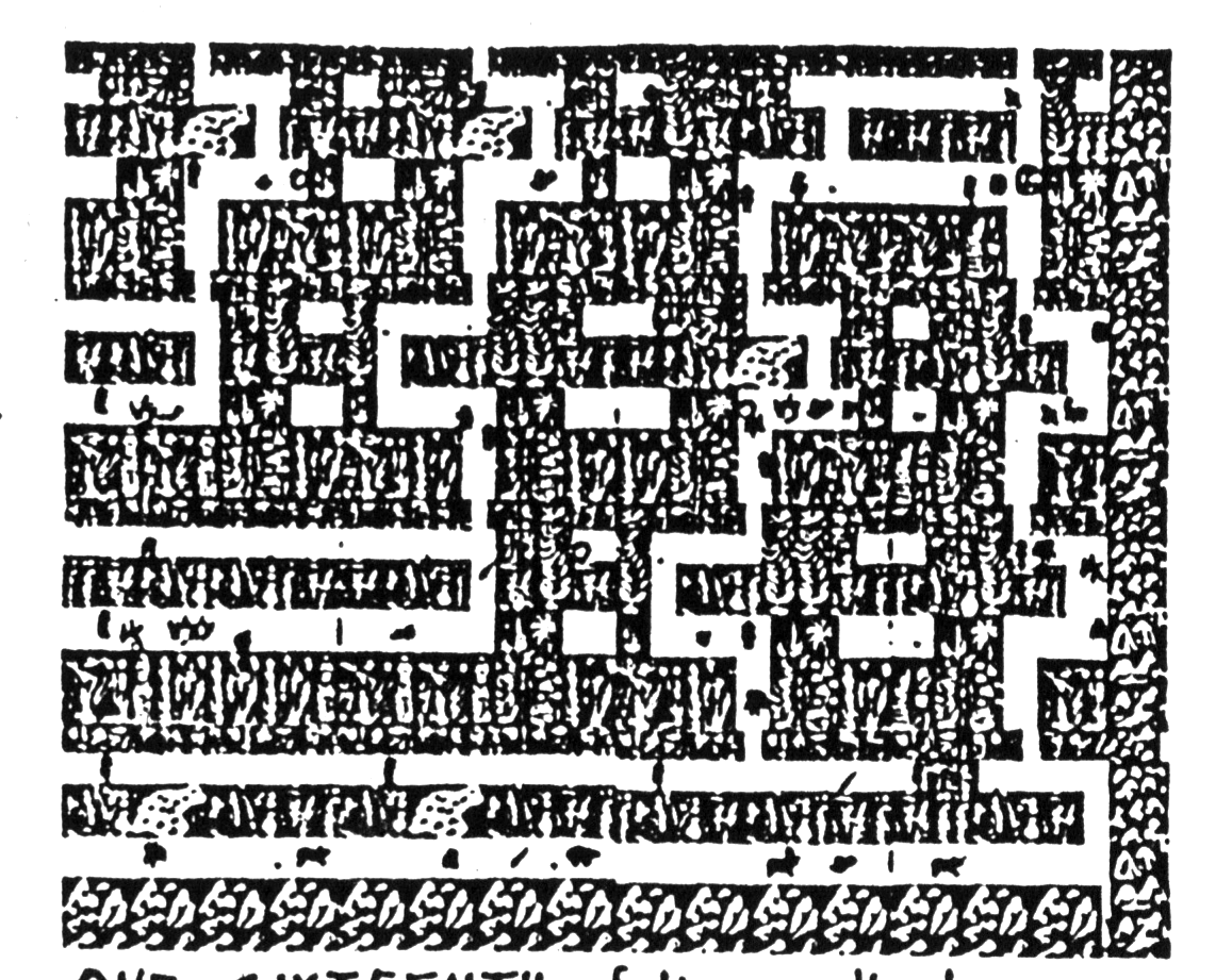
Listing 5 is the Spectrum version of the corrected code. We’ll leave the TS2068 version as an “exercise to the student”. Substitute this program for the NMI screen copy given last time, following the EXACT same procedure before loading it. This time, you should be able to produce as many screen copies as you want. As an example of its use, a 16 – screen portion of the SABRE WULF map is included here.
Listing 6
 100         ORG   #3C00
 110
 120 ;THE NORMAL NMI PUSHES
 130         PUSH  AF
 140         PUSH  HL
 150
 160 ;  SAVE AN ADITIONAL REGIST
ER
 170         PUSH  BC
 180
 190 ;GET BACK OLD INT STATUS
 200
 210         LD    HL,NEXT
 220         PUSH  HL
 230         RETN
 240
 250 ;THE RETN CAUSES US TO CON
TINUE HERE
 260
 270 NEXT    LD    A,R
 280         PUSH  AF
 290
 300         DI
 310         LD    B,#C0
 320         CALL  #0EAF
 330         DI
 340
 350 ;RESTORE PROPER INT STATUS
 360         POP   AF
 370         JP    PO,DONE
 380         EI
 390
 400 DONE    POP   BC
 410         POP   HL
 420         POP   AF
 430
 440 ;INT STATUS HAS ALREADY BE
EN RESTORED
 450 ;SO WE DON'T USE RETN
 460
 470         RET
Listing 6 is the new NMI handler, and it’s incredibly whacky. Let’s check it out. The PUSH AF and PUSH HL are standard for NMI, and we’ve added another to do the same to the BASIC registers, since the ROM COPY routine will change them. This isn’t bad so far, but readers who tried to redo the routine to copy the screen without messing the interrupts will have had lots of trouble. We’re going to “sneak around” the problem.
Recall that the reason we didn’t want to fiddle with the maskable interrupts is that their status (which is saved when an NMI occurs) would then be corrupted, and it might not be restored properly when we execute our RETN. The trick, then, is to find out what the status was, save it where we can get at it, and then restore it OURSELVES, before we return. This requires tricks that the “learning machine code” books just don’t cover. Still, once we’ve done them, they work fine, and we can EI and DI to our heart’s content.
The trick begins with the LD HL; NEXT; PUSH HL; and RETN lines. Note that “NEXT” is the address of the instruction following this group, and so executing it simply causes us to continue on to the next instruction. However, it also restores the ORIGINAL INTERRUPT STATUS.
The instructions LD A,R and PUSH AF appear entirely useless. But if we look carefully at the flags that are affected when we use the R register, we see that the interrupt status is put into the P/V flag. Now we have the interrupt status, and we preserve it with a little “PUSH”.
The next 3 instructions call the screen COPY routine in the ROM, like last time. After the CALL, we do a DI; POP AF; JP PO; DONE and EI. These restore the interrupt status. Note that we popped the flags that contained the interrupt status, and so the jump instruction has nothing to do with parity. The “parity flag” in this case is telling us whether the maskable interrupt should be enabled or disabled, and we jump accordingly.
We then restore the registers we’ve changed, and return to the code where it was interrupted. Note that we used a RET and not a RETN. This is because a RETN would restore a corrupted interrupt status. Since we’ve already restored it properly, we must instead use RET, which then leaves it alone. That’s it!
Be aware that if your NMI switch is too bouncy for the capacitor to handle, it could cause two NMI pulses to occur. If this happens, the second one can corrupt the maskable interrupt status irreparably. Also note that this routine (and the ROM COPY routine) put a lot of entries on the stack. Unfortunately, a lot of Spectrum games are first developed on TRASH-80 computers and switched over after they’re debugged. (Some nonsense about productivity due to good keyboards, development tools and disk drives; it’s hard to believe.) As such, the stack sometimes ends up in odd locations, and if you put too many things on the stack you may over write some machine code or variables. (Stack space doesn’t come for free, gang.) This means that you may notice odd behavior in some programs after using even this corrected NMI COPY. Life is tough, but SABRE WULF has sure gotten easier!
As usual, I’m glad to get your letters and phone calls. You can write to me, Wes Brzozowski, [address omitted]. Please enclose a stamped, self addressed envelop if you wish a reply. Feel free to call at [phone number omitted], but please call before 9:30 pm Eastern Time.
That’s all until the big finale next time. See you then!