Authors
Publication
Pub Details
Date
Pages
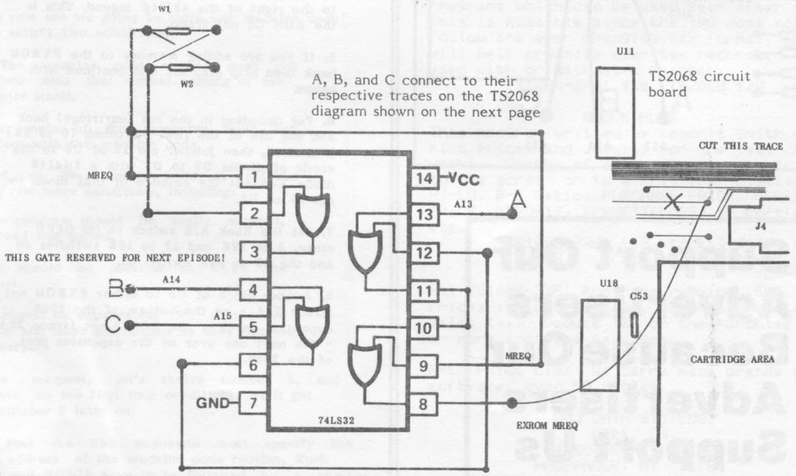
The following circuit will allow you to use the memory area above the EXROM, which ocupies the 0 to 8K chunk in that memory bank, as RAM.
Cut the traces from pin 22 of the Exrom (mreq) and install the circuit in Figure 1. The easiest place to put this modification is a little left of the cartridge board connector, on the component side of the board.
Use an ohm meter to find the doughnut (just left and slightly above the cartridge connector) that connects to pin 22 of the exrom. Cut the trace just left of the doughnut and solder the output (pin 8) of this circuit to the doughnut.
Solder pin 9 to the other side of the cut. Just left of the 16 K ROM, below the 64 pin ULA chip and to the right of the Z80 chip, you will find two blue zero ohm resistors (jumpers) with single black stripes marked W1 and W2. The left side of W1 is an easy place to make this solder connection for pin 9.
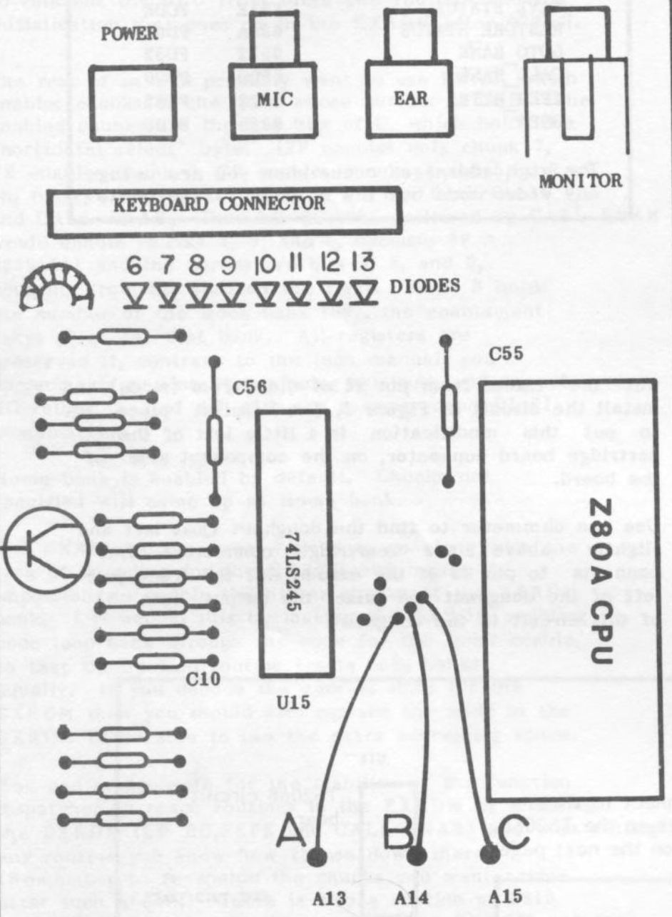
- A13 = Z80 pin 3
- A14 = Z80 pin 4
- A15 = Z80 pin 5
- MREQ = Z80 pin 19
Image Gallery