
Yesterday the November ’92 Sinc-Link came along with the Out-of-town newsletter. George mentioned that a couple of members are looking for AERCO type printer interfaces.
Some time ago I realized that a feed-thru connector would improve the I/Fs usefulness. I had also wished for a longer cable than the one supplied with mine. Since we have several IBMs in the house I decided that an IBM style connector would be more convenient. Then I could use a cable I already had. So I made a duplicate using solder type sockets connected with wire wrap wire as the hook-up wire. I had a 90 degree connector and all the chips from previous projects, except for one-the 74LS273. I had a 74S273 that I thought I would use temporarily until I could get the correct chip. (It has been close to two years now but I still plan to replace it – someday.)
Below is the circuit diagram:
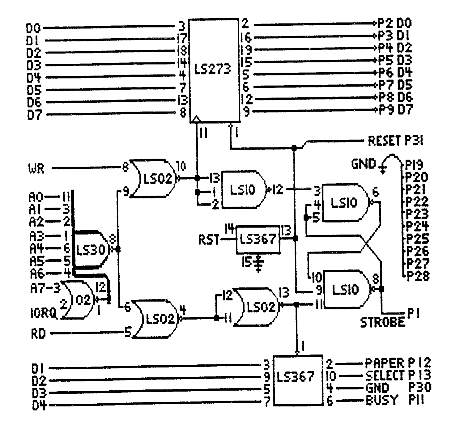
As you can see I am still trying to use Pixel Print for my articles and to try to draw a schematic with ArtStudio is pressing the issue a little bit. In case it isn’t clear I was trying to indicate that LS02 pin 1 connects to pin 12 of LS30
I built the unit on a piece of perf board with holes on .1 in. centers. I used sockets because I don’t like to solder to ICs, but sockets aren’t necessary. There are two isolation capacitors that go across the ground and the +5 busses. Of course the highest numbered pin is the +5 volt connection and the diagonally opposite is the ground connection and is not shown on the schematic. The only other parts required are a TS type edge connector(s) to which the right hand connections are made. The printer cable numbers are the P numbers down the left side of the schematic. The component layout that I used is shown in the sketch shown below. I don’t think any of this is critical and it could be made smaller if you did not choose to use an IBM style (25-position D-subminature) connector.
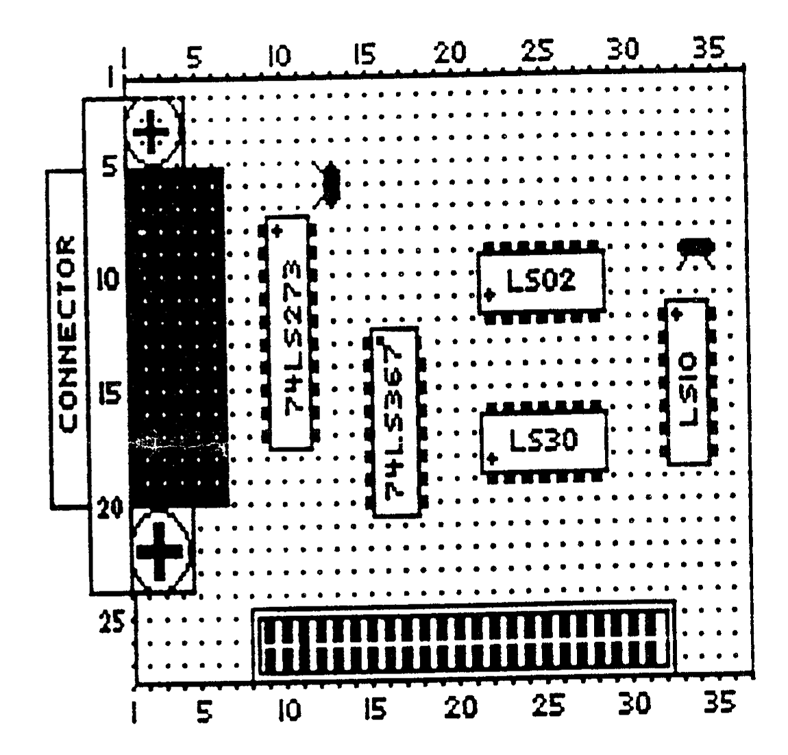
The view is what you see looking over the keyboard at the female edge connector. The isolation capacitors are .1UF discs.
The schematic shows the final printer parallel connector pin numbers. If an IBM style D-mini is used the following chart will decode them:
            parallel
1 2 3 4 5 6 7 8 9 10 11 12 13 14
1 2 3 4 5 6 7 8 9 10 11 12 13 14
              IBM

            parallel
15 16 17 18 19 20 21 22 23 24 25
-- -- -- -- 18 19 20 21 22 23 24
              IBM

            parallel
26 27 28 29 30 31 32 33 34 35 36
25 -- -- -- -- 16 15 -- -- -- 17
              IBM
Les Cottrell [address omitted]