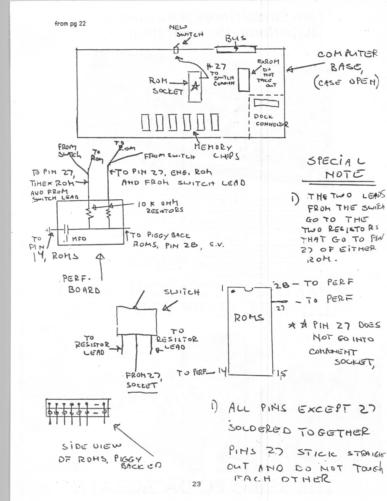
You will need a piece of perf-board, about 2 inches by 1 inch, holes on .100 center, two 10K ohm resistors, one . 1 MFD capacitor, one single pole double throw switch, 5 feet wire wrap 30ga.
Remove the TIMEX ROM, making sure not to remove the EXROM (see drawing), and place on non-conductive foam.
Make up the 1 x 2 inch component board and place the resistors and capacitor on it as per drawing. Be especially careful that you know which leads are which!
Solder a wire to the ROM socket on the 2068 computer board, to pin 27, and take this wire to the common lead on the switch, which should be put through the case by the monitor RCA plug. There is room for this by this area, and it will be out of the way when you are using the machine.
You should then solder the pins of the two ROM’s together, attaching all except pin 27. These two pins should stick straight out from the piggyback unit, and one lead of each should go to the side of the resistors that are opposite the power coming in from pin(s) 23 of the ROMs.
One side of the capacitor has to be taken to signal ground, which is Pin 14 on the ROMs.
After you have made all the connections to the perf-board, wrap the entire unit with tape to prevent any wires or contact points from shorting out to the case, or other components.
After you have soldered the ROMs together, made all conections to the switch, perf-board and the ROM socket, replace the ROM unit and close the case up. I would suggest that you replace the ROM unit in the socket before you solder the the connections to pins 27, pin 23 and pin 14, this will make it easier to judge how long the wires should be.
Also, install the switch before you solder the wires to the leads. The two ROM’s will piggyback snugly, and should be next to each other. It is a tight fit when the case top is replaced, and the top of the piggyback POM unit touches the top piece which is the keyboard.
If you follow the plans, do not have any cold solder joints, you will have no problems in making this conversion. Also, whenever you change from one ROM to another you should turn all power off, throw the switch and power up again.
Image Gallery