I’m sure that you are all aware by now that it is possible to run most Spectrum programs on a 2068. Some will run without modification and some will not. As indicated in the last issue (Games review, SWN 2/3), if a program stops due to an illegal RAMTOP (too low), then changing the CLEAR 24000 or so, to CLEAR 28000 or so, may allow the program to load and maybe execute as well. Self-contained programs (ones that make no specific routine ROM calls) will most probably run. If a lot of ROM calls are made, then they will not.
Enter, the Spectrum ROM. Now it becomes necessary to install a Romswitch, EMU or ROM into your computer. At this point, most (well written) programs for the Spectrum will run. Then, there are the rest. The true hacker on a ZX machine has been well groomed to write efficient code, compact subroutines and use all the tricks possible to speed up the program or otherwise make the program unique.
One such trick (and the one we can fix) is to assume that all Spectrums (in this case) act the same. Since the 2068 does not act like a Spectrum in its entirety; thus the problem emerges.
With the help of a lot of people and a lot of time invested, a partial solution has evolved.
First, the problem: The Spectrum (issue 3) puts an FF on the data bus (like the ZX81) after null keyscans or while it is just waiting with nothing to do. The 2068 does not.
The reason: All the data lines in the Spectrum have 10K ohm pullup resistors on them (like the ZX81). The 2068 does not. Only data line 2 is pulled high on the 2068.
The quick and dirty solution: Add 10K pullup resistors to the data lines.
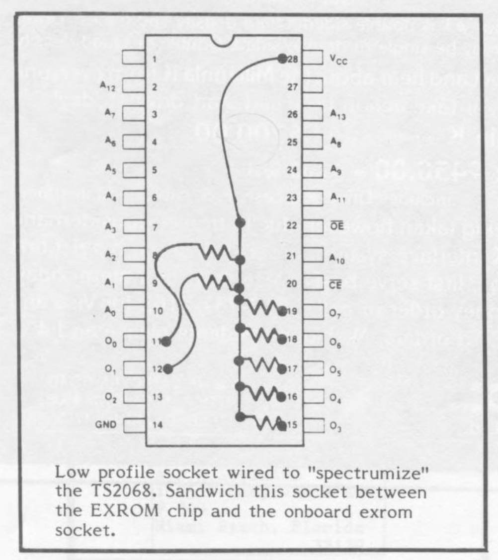
The easiest place to make this modification such that if you screw up, you will not damage your machine in any way, is to use a 28 pin low profile socket and install it under the EX ROM. Use the following pinout diagram to make the proper connections. You will need 7 resistors. I suggest using an in line resistor pack that has one common lead (not available from radio shack). This pin will be tied to +5 volts. This modification will not affect the running of any 2068 programs that I know of.
Remember, when you turn the socket over, you will have the mirror image of the diagram. It will therefore be necessary to solder on the opposite side as it appears here.
Hold the resistor pack so that all the pins are pointing up and the common pin is pointing away from you. Bend the first 5 pins (not the common pin) about 30 degrees to the left. Bend the rest of the pins (including the common pin in the other direction and all the way back over the side of the pack. Turn your socket over and use an alligator clip to hold the pack in place so that those 5 pins rest just on the lip of the socket over the data lines 3 to 7.
Remember, after you do the soldering, the socket must fit snugly, so don’t use gobs of solder. After you tack down those 5 pins, you can remove the alligator clip.
Use 30 gauge wire wrap wire to jump DO and D1 to two of the pins that you bent back.
Jumper the common pin to pin 28 of the socket. Open your case and locate the EXROM. It is the big chip above the cartridge bay. Pry it out and insert it into your “Spectrumized” socket.
Reinstall the circuit into the EXROM socket. Close up your case.
Testing the mod: The machine will run in the Spectrum mode whether your mod is correct or not. To test it, you must be in the 2068 mode. If the screen keeps reinitializing, then you goofed. If it comes up properly, then try booting one of those Spectrum programs (in the Spectrum mode) that previously did not work.
My thanks goes out to Bill Russell, John Oliger, John Brown, and Ray Kingsley.
Image Gallery