
ZX-81 MIDI INTERFACE PROJECT
In the next few issues I will be describing the design and construction of a ZX-81 computer interface to connect to MIDI equipped musical equipment. Hopefully some members will become involved in developing software and applications for this project.
If your using your ZX-81 for a doorstop, and you have a MIDI equipped music keyboard ( or any MIDI device that is ), let’s make a MIDI interface and start making music.
MIDI ( Musical Instrument Digital Interface ) equipped keyboards and devices have been around for quite some time now. These devices are characterized by the presence of MIDI IN and OUT ( usually accompanied by MIDI THRU ) jacks using a standard D.I.N. 5 pin female chassis connector. The idea behind these jacks is that different manufacturers of electronic musical equipment have standardized on an information exchange format. This allows you to connect a KORG synth keyboard to a YAMAHA keyboard and the note values played on the KORG will activate the YAMAHA.
This by all means is barely scratching the surface of what’s possible. The MIDI standard allows for much more than simple note data exchange, it also is used to synch up drum machines and sequencers to play stored rythm patterms and music previously entered. These devices are all microprocessor based and connecting a computer up to them reveals the ultimate music system, the possibility of total control. Facilities exist in the software protocol that standardize parameters for control of the sounds the synthesizers produce as well as dumping this data to store it somewhere else ( or load it for that matter ). Some manufacturers have hinted that around the corner are MIDI light shows and special effect units such as lasers and MIDI mixers.
Some might say that the ZX-81 is not suitable for this application due to several disadvantages such as memory and speed constraints. Expanded to 64k and running ML software will yield a system at least as powerful as the 64k APPLE system I’ve been using for years. Even unexpanded units would offer at least a MIDI scratchpad to write small sequences or send specific MIDI information ( such as program editors for synth voice creation ).
The interface protocol as described in the MIDI specification 1.0 is an optically isolated, serial ( 31.2kBAUD ) format, 8 bit data ( 1 start bit, 1 stop bit ) connected as shown in diagram 1. The MIDI OUT jack has pin 2 (note the odd pin numbering used on D.I.N. connectors) connected to ground; the shielded twisted pair cable used for interconnection has its shield connected to this pin. Pin 2 on the MIDI IN jack has no connection to this pin, and since the interface is optically isolated this provides protection against ground loops that plagued earlier systems of musical data exchange. Pin 4 is always most positive and pin 5 most negative. No connections are made to the other pins. The current is limited to a maximum of 20 mA. All these specs are part of the MIDI standard document 1.0 agreed upon by all the major manufacturers.
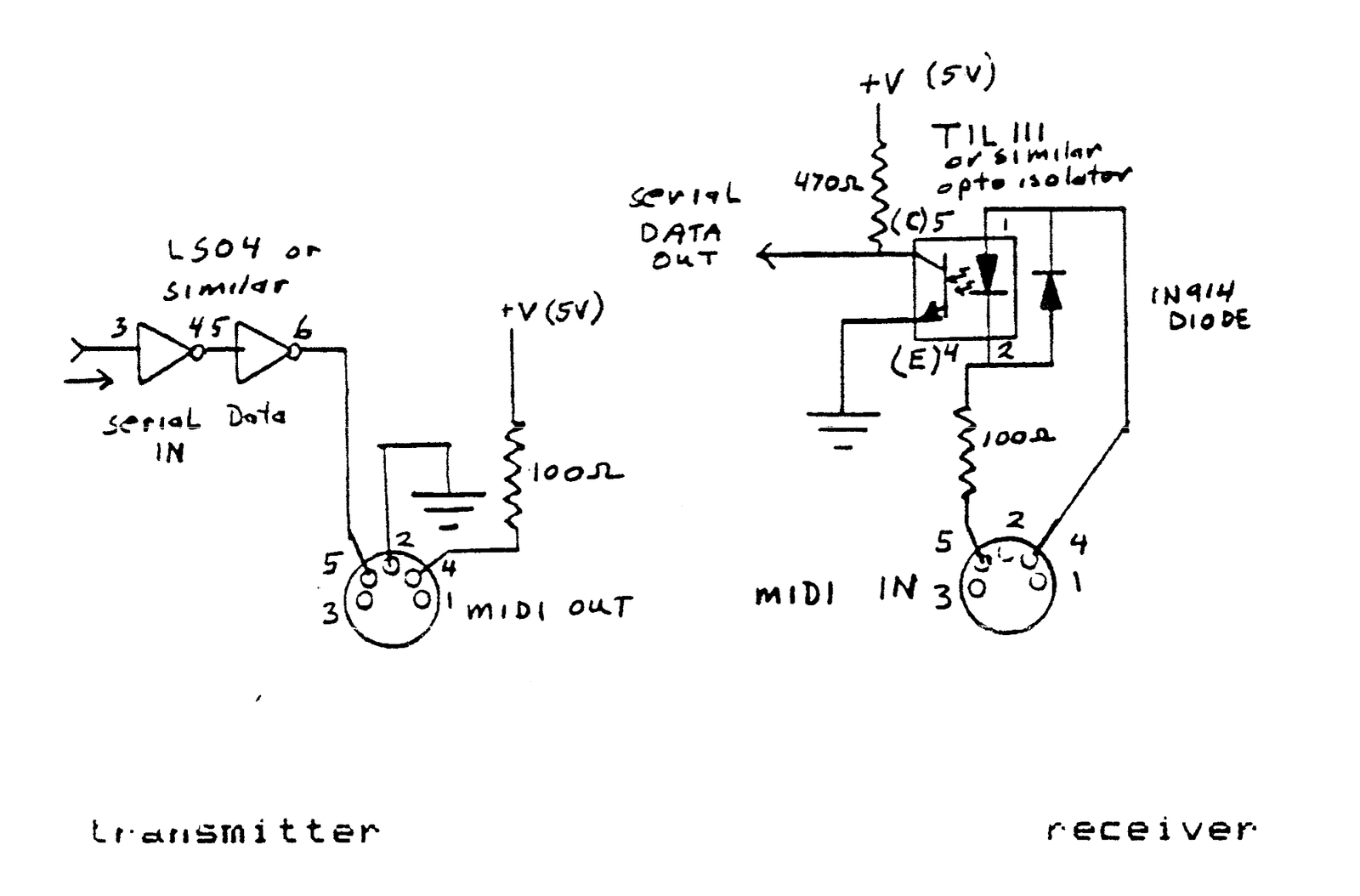
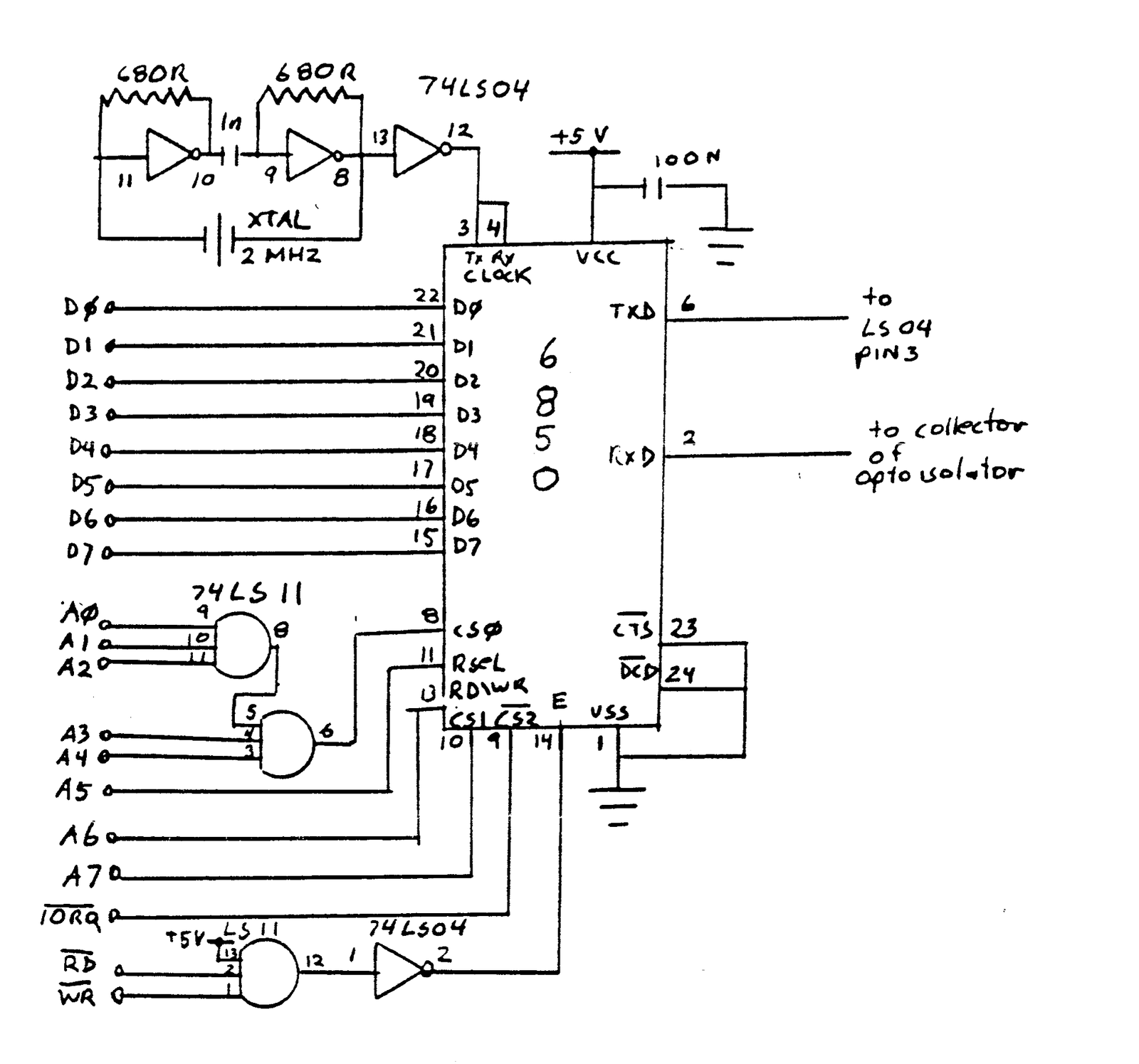
Obviously, the control system of any one of the instruments ( or data handlers, or slave synths etc. ) would have to be microprocessor driven UARTs or ACIAs ( chips that convert the parallel data from the CPU to the serial data in the MIDI format ). I have chosen to use the popular Motorola 6850 ACIA which will give us a send and receive port ( MIDI IN MIDI OUT ). The circuit is shown in diagram 2.
The board can be assembled on traditional perfboard and wire-wrap is recommended in this case, or more elegant and sturdy, a pc board could be constructed. I hope to present in a future issue a PCB layout for this project.
On the software side the board appears as a Z80 I/O port with the CONTROL register at address 9F hex or 159 decimal. As the software boots it must reset the ACIA by writing a number with the two least significant bits high as 3 ( hex or decimal ) then initialize the chip by writing a 56 hex or 86 decimal to this location ( this sets the byte size and clock divisor ).
The data are sent at address BF hex or 191 decimal and received data are available at address FF hex or 255 decimal. In addition there is an ACIA STATUS register that is at address DF hex or 223 decimal. A chart in diagram 3 shows what should be expected at each register.
DATA   RECV AND    CONTROL REG      STATUS REG
BUS    XMIT DATA   WRITE ONLY       READ ONLY
LINE   REG
------------------------------------------------------
D0     BIT 0       CLOCK DIV 1      RECEIVE REG IS FULL
D1     BIT 1       CLOCK DIV 2      TRANSMIT REG IS EMPTY
D2     BIT 2       WORD/PARITY 1    DCD
D3     BIT 3       WORD/PARITY 2    CTS
D4     BIT 4       WORD/PARITY 3    FRAMING ERROR
D5     BIT 5       XMIT CONTROL 1   RECEIVE REG OVERRUN
D6     BIT 6       XMIT CONTROL 2   PARITY ERROR
D7     BIT 7       RECEIVE INT      INT REQUEST
Diagram 3 : ACIA register contents
As can be seen by examining the chart the transmit and receive registers are pretty straight-forward but one might be confused looking at the other two lists. First of all, the CONTROL registers parameters for MIDI use have but one possible setting as described previously so understanding this list is not necessary. However some use might be gotten out of the STATUS register, for instance it can be checked for a “1” at D0 to see if a data byte is ready to be read into the CPU. Likewise a “1” at D1 indicates that the transmit register can be loaded with another byte as the previous one has now been sucessfully transmitted. The rest of the STATUS register can be ignored ( perhaps the framing error can be of some use but probably only in more sophisticated software ).
Since the ZX-81 has no IN or OUT commands, two short machine code routines will have to be written to access the interface from Basic. Also Basic is far too slow for serious work with the unit as a data recorder so most of the real work will have to be done in ML anyway. I hope to have the interface working with the Larken Disk System to save and load MIDI files, I also figure I’ll need to use a 64K ram to have enough room to do serious work with the system ( such as MIDI multitrack orchestration etc. ) the data can simply be written into the upper 32k area and read by the program running in the “normal” 16k block with the Larken interface inhabiting the 12-16k area. Perhaps a 4k scratch pad ram could be allowed for medium res graphics for music editing ?
In the next installment of this series I will describe the MIDI data protocol and present some short ML test routines that run from basic. Till then, I encourage the interested parties to obtain the necessary parts and try to wire-wrap a prototype. I don’t suggest making a board yet because the addressing may change if it interacts with the Larken boards.
TILL NEXT TIME —-HACKER’S HAVEN LOGGING OFF BYE