The cartridge dock of the 2068 was Supposed to open up a whole new dimension in instant loading software when Timex introduced it oh so long ago. There were very few cartridges available and what was wasn’t worth it. Then came along Doug Dewey’s Spectrum emulator which made excellent use of it. Now more recently, OS-64 from Zebra demonstrates another good example.
The cartridge dock supports LROS (Language ROM Oriented Software) and AROS (Application ROM Oriented Software). The Spectrum emulator and OS-64 are both good examples of LROS and all the programs such as those put out by Timex, Sunset Electronics, and Tom Woods’ ProFile on cartridge are all good examples of AROS.
With this EPROM programmer, you can develop your own LROS and AROS Cartridges. The EPROMs will plug into Doug Dewey’s EMU series, Sunset’s EPROM boards, and Foote Software’s Printer interface EPROM socket.
The programmer will program 2764 (8Kx8) and 27128 (16Kx8) EPROMs and with some Slight modification, will program the 2716, 2732, and the 27256 EPROMs. The 2068 and Spectrum ROMs are the 27128 configuration and the 2068 extension ROM is configured as a 2764.
You need to use 250 or 300nS type EPROMs which are designated as 27128-25 or 27128-3. This is the highest speed at which they will operate and must be able operate faster than the 2068 will access them so they can keep up!
To program these particular EPROMs, you need a 21 volt programming voltage. The 2068’s power supply is rated at 15 volts with a one amp load. With nothing connected, it measures 22-23 volts. With it loaded down by a 2068 and a printer interface, disk drive and this interface, it measures between 20 and 20.5 volts. I have been using this voltage to program EPROMs and have had no trouble.
I checked a number of 2068s and power supplies to see if these findings were consistent, they were, so the 2068’s power supply should work well for you too. If for some reason it does not, the TS2040’s power supply and a regulator circuit will work fine.
Programming the EPROM is a fairly Simple task of providing the 21 volt programming voltage, setting the address lines to the desired address you wish to program data to, placing data on the data lines and then making the program line go low for about 50 mS (1/20 sec).
With this interface, you can set the starting address of the EPROM where you want the programming to begin, set the Starting address in the computer’s memory you wish to program from and set the number of locations you wish to program. A very simple system that will allow you to use this interface with any Sinclair computer or other computers for that matter as long as the correct programming voltage is supplied to the EPROM.
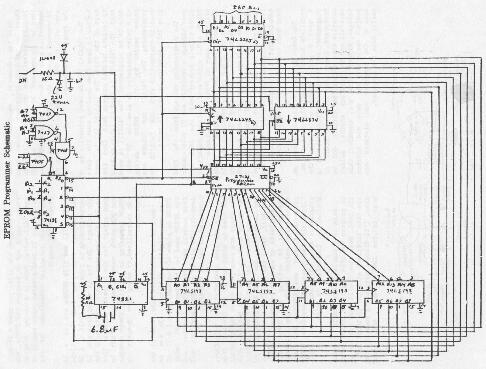
The heart of the programmer is the decoder which creates the ports from which control to different parts of the programmer are obtained. I chose a 74LS138 3 to 8 line decoder which I used to fully decode I/O ports 0-7. Not all the ports are needed, so a few can be used for another project later. I chose the following ports for this project:
- PORT 0: READ EPROM
- PORT 2: LOW BYTE ADDRESS
- PORT 3: HIGH BYTE ADDRESS
- PORT 4: PROGRAM EPROM
- PORT 5: INCREMENT ADDRESS
Because we are programming a 14 bit EPROM from an 8 bit source, we must load the EPROM starting address in two steps. First the lower 8 bits and then the upper 6 bits. If we want to start at say address 10,000 decimal (2710 hex), we need to load the high byte as OUT 3,39 (27h) and the low byte as OUT 2,16 (10h). How do we come up with those numbers? High byte = Low byte = 10,000-256*INT(10,000/256)=16. You can convert these numbers to hex by looking in appendix B on page 239 in the 2068 User’s manual.
From the schematic, we can see that these low and high bytes are loaded into 74LS193 presettable counters which can then be incremented by sending an OUT command to port 5. Port 0 is used with the IN command to read the EPROM and port 4 is used with the OUT command to write data to the specified address.
The 74LS245 (a) is used primarily as a buffer to keep from loading down the data buss of the 2068. The 74LS245 (b) is used to isolate latched program data from the buss. The 74LS374 is used to latch or hold data to be programmed. The 74LS221 is used as a pulse generator to give the 50 mSec pulse needed by the EPROM during programming. The 74LS27 and 74LS0O8 are used in conjunction with the 74LS138 to give full decoding of the I/O ports.
The programming voltage from the 2068 goes through a resistor and 22 volt zener diode to help protect both the 2068 and EPROM. A 0.1 microFarad tantalum capacitor helps cut down on transient voltages and five volts feeds the line through a diode so that the EPROM can be read when not in .the program mode. I tried lowering the program voltage some to see how much effect it would have and found that I could go as low as 18 volts and still have reliable programming. This may vary from manufacturer to manufacturer though. I have been using Hitachi # HN4827128G-25.
The Zebra Systems Protocard makes an excellent board to mount this project on. I used a proto board to develop the programmer and later transferred it to a Protocard. Keep the leads as short as possible when wiring the circuit and be careful not to cause any shorts, solder bridges, frayed wires, etc. Remember, this project deals with the data and address buss of the computer and mistakes can easily ruin the computer.
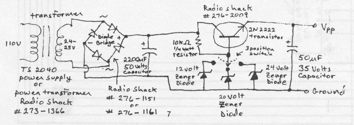
To program the 2716, you need a 25 volt power supply and to program the 27256, you need 12.5 volts. Here is a wiring diagram to use the TS 2040 printer power supply or any 25 volt secondary transformer for the programming supply.
The 2716 and 2732 EPROMs are in a 24 pin package with pins 1-12 & 13-24 corresponding to pins 3-14 & 15-26 of a 28 pin package. The Vcc is moved from pin 28 to 24. All the pins remain pretty much the Same except for the highest address line and PGM which move some from EPROM to EPROM depending on its size. These changes can be realized by using wire jumpers or switches.
Because the 2068 uses ROMs, some of: the pins are slightly different. To use an EPROM in place of the ROM, pins 1 & 27 of the EPROM need to be bent upward (away from socket) and connected together and connected to pin 28 so that they are all connected to Vec (5 volts).
Once you have completed the interface, you need to learn how to get the most from it. There are some good books and programs out there that would be most helpful with this programmer. For machine code writing and de-bugging, Hot-Z by Ray Kingsley, PO Box 8032, Santa FE, NM 87504 is a must. It is available on tape or cartridge. Sunset Electronics is selling a 2068 ROM disassembly manual which also covers programming your own EPROMs, and John Oliger also has plans and complete EPROM programers also. His address is: 11601 Whidbey dr, Cumberland IN 46229.
Here is a simple little BASIC program to program the 2764 and 27128 EPROMs with the 2068. Next time I will show you how to use this interface with the TS 1000/1500. Also, I’ll discuss correcting some of the bugs in the 2068 home ROM, and transferring your own programs to EPROM.
Image Gallery