
You can operate virtually any electrical device in your house with your ZX81 or TS1000 computer, an inexpensive wireless home controller, and an adaptation of the circuits used in my “Robotics on a Budget” article (SYNC 3:4).
The control system adapted for use in this project is the BSR X-10, available through several sources including Heath and Sears. The control modules which are connected to lamps, appliances, or wall switches, receive a signal transmitted over the house power wiring and thus require no direct hookup to the computer. The controller is available for around $35 and the modules for about $17.
Modifying the BSR X-10
To modify the BSR X-10 for this project, first remove the screw from the deep hole in the center of the bottom of the X-10 case. The two halves of the case will then pull apart. Now remove the circuit board from the top half, with the 28 pin IC on it, by first removing the five screws.
Be careful to keep the keyboard upside down (IC upright) because, when you remove the circuit board, there will be nothing to keep the keypad buttons from falling out.
After the screws are removed, carefully pry the circuit board out and turn it over to expose the foil circuit side of the board (Photo 1). The total IC pinout to the keypad switches is listed in Figure 1. Prepare eleven hookup wires each about 6″ long. Solder one end of each to an IC pin circuit foil (see Figure 2 and Photo 1). After the wires are soldered, push them flat against the board and bend them over the edge of the board as shown in the photo. Then push the board back into the top half of the case. There will just be enough room for the wires between the case side and the board edge (Photo 2) if all wires are lined up and none overlap each other.
Figure 1. BSR X-10 Control IC Switch Pinout.
Switch           Control IC Pins
1                 1     17
2                17     28
3                 1     20
4                20     28
5                 1     18
6                18     28
7                 1     19
8                19     28
9                 1     16
10               16     28
11                1     27
12               27     28
13                1     21
14               21     28
15                1     26
16               26     28
ON               20     25
OFF              25     27
BRIGHT           19     25
DIM              25     26
ALL LIGHTS ON    18     25
ALL OFF          21     25
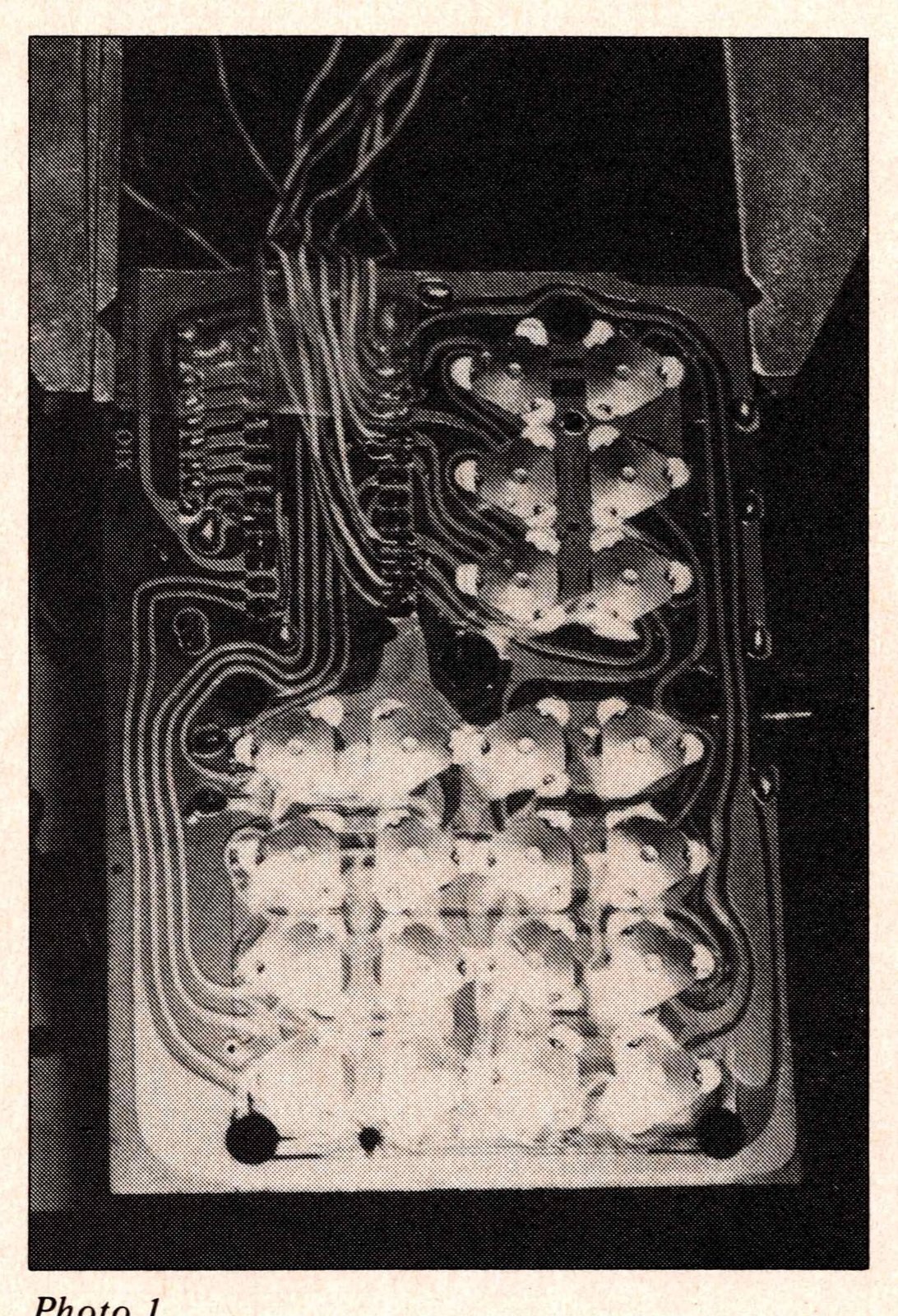
Figure 2. BSR X-10 Switch Control IC.
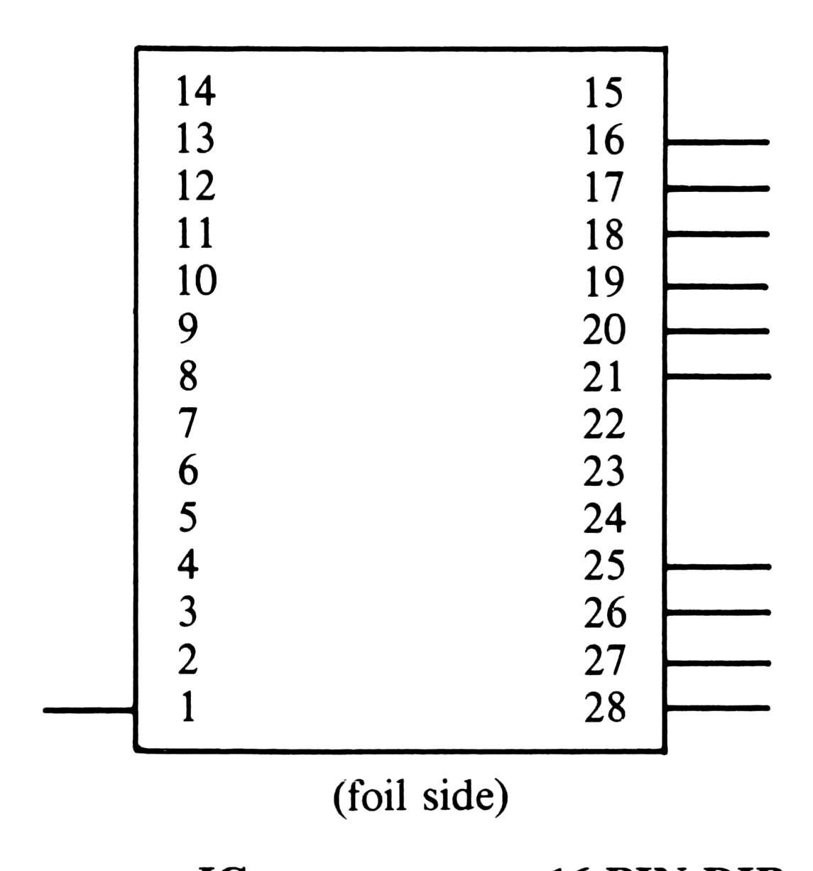
IC                 16 PIN DIP
CONNECTION   to    JUMPER SOCKET
1                  1
16                 2
17                 3
18                 4
19                 5
20                 6
21                 7
25                 8
26                 9
27                 10
28                 11
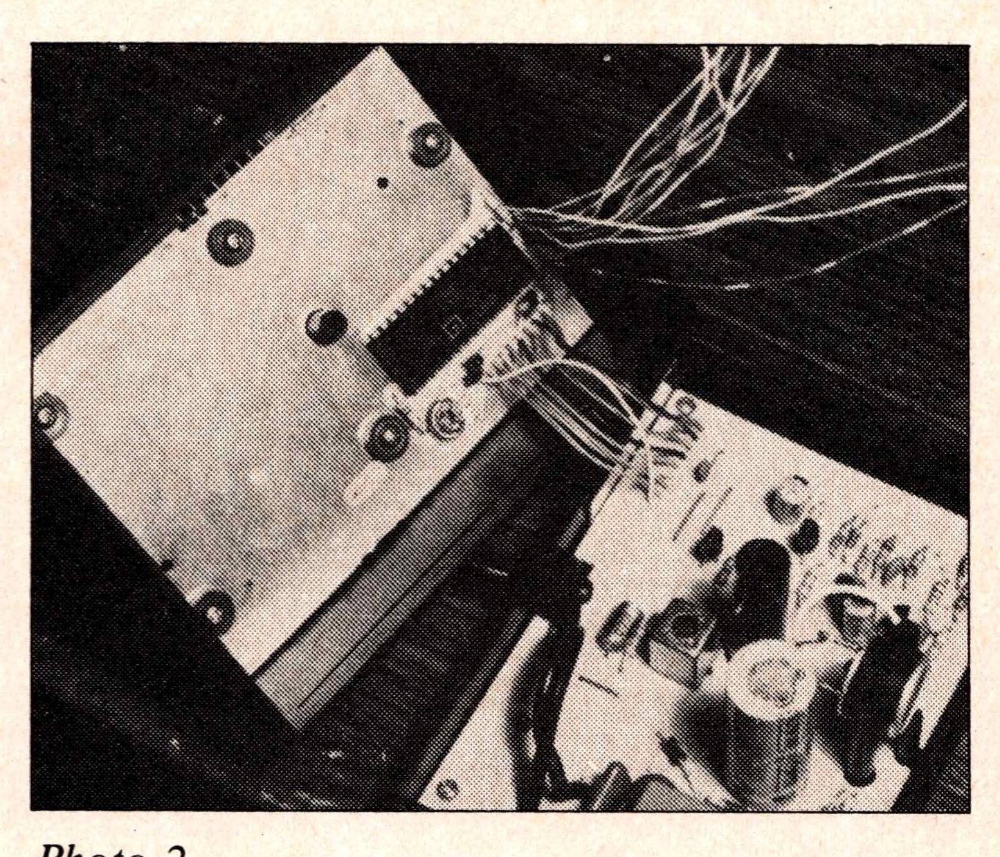
The RX81 board drives a Darlington transistor array, activating 5V 14 pin DIP relays which switch the BXR Z-10.
Be careful that you do not dump out the keypad switch buttons. Keep the top half of the case upside down until the board is all the way back into the case top. When you see that it fits (you have formed the wires against the edge of the board), remove the circuit board again.
Next, cut a small rectangular hole in the side of the case or drill some holes so that a 16 pin DIP socket can be attached later to the outside of the case with the hookup wires from the IC soldered to it. The jumper pinout is listed in Figure 3. Now pull the wires through the hole in the case as you replace the circuit board into the top half of the case for the final time (Photo 2).
Next, cut the hookup wires about an inch long outside the hole in the case and solder them to the DIP socket (Photo 3 and Figure 3). Then glue or otherwise fasten the DIP socket to the outside of the case.
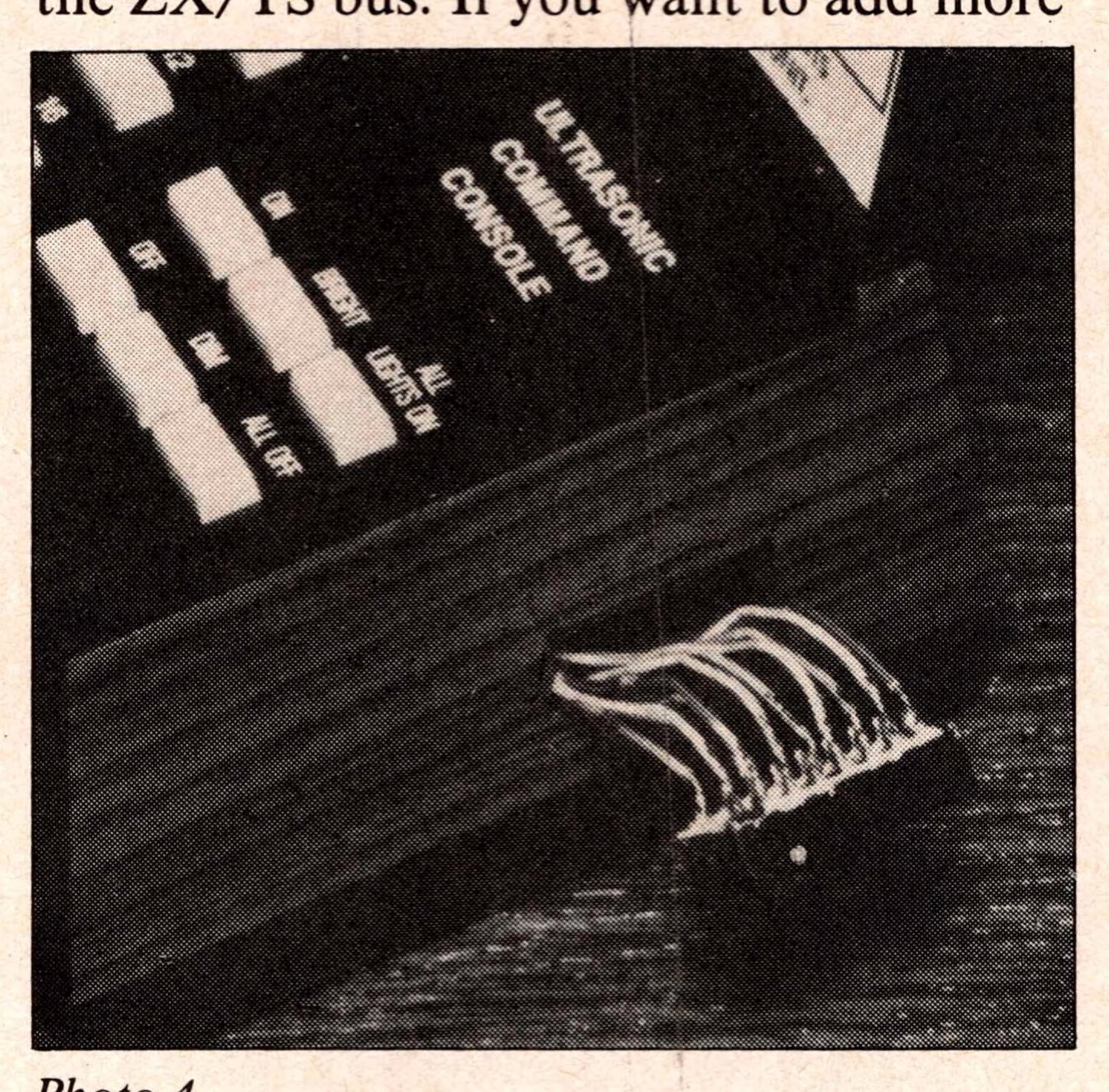
You have now completed the modification to the BSR X-10. After the rest of the project is finished, you will be able to plug a DIP jumper cable into the socket on the X-10 (Photo 4).
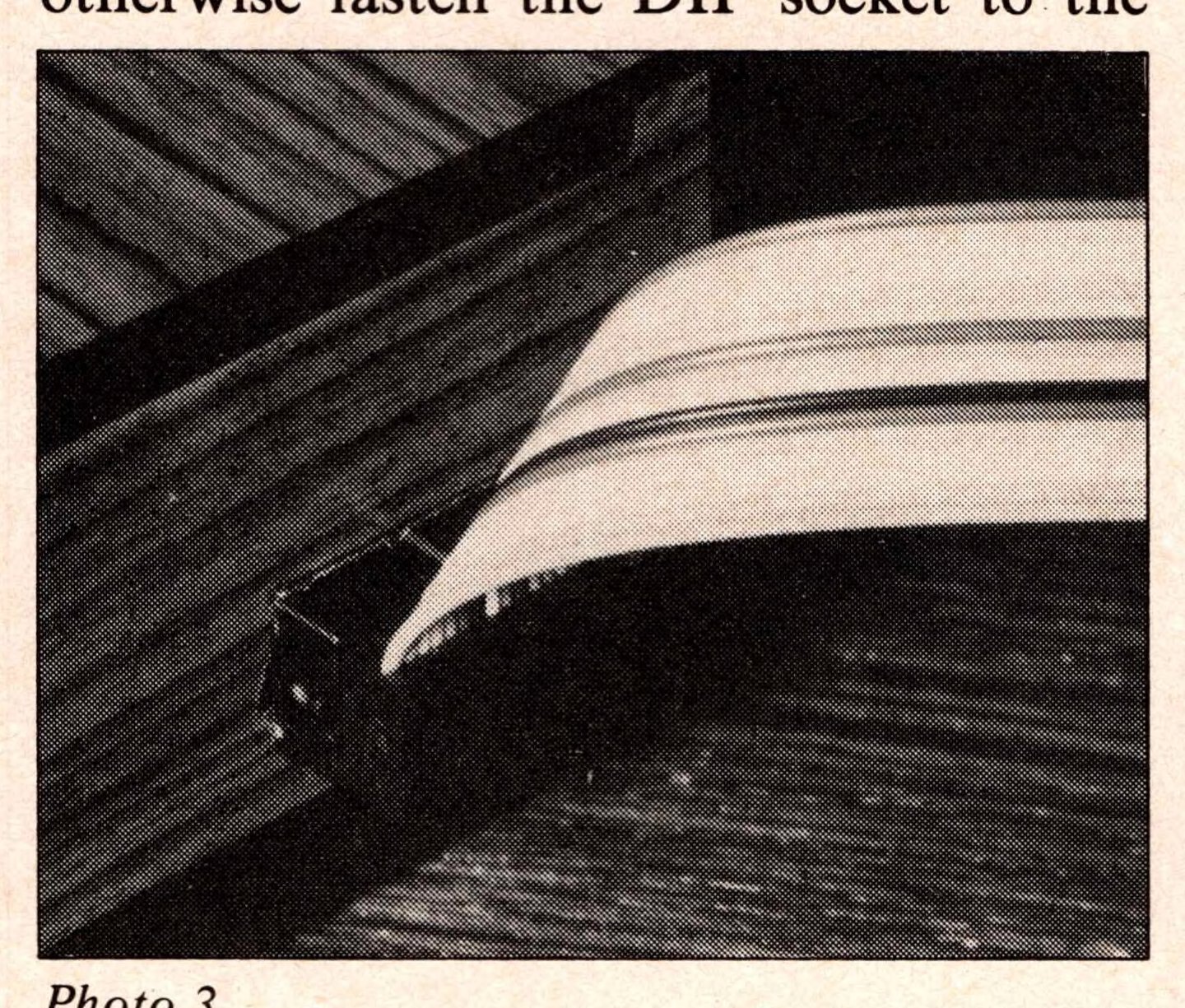
Figure 3. Summary of Switch Connections to 16 Pin Jumper.
SWITCH           JUMPER PINOUT   RELAY #
1                 1      3        1
2                 3     11        8
3                 1      6        9
4                 6     11       10
5                 1      4       11
6                 4     11       12
7                 1      5       13
8                 5     11       14
ON                6      8        2
OFF               8     10        3
BRIGHT            5      8        4
DIM               8      9        5
ALL LIGHTS ON     4      8        6
ALL OFF           7      8        7

Pinout for remaining switches not used in this project
9                 1      2
10                2     11
11                1     10
12               10     11
13                1      7
14                7     11
15                1      9
16                9     11
The Boards
For the interface between the BSR X-10 and the computer I used the Zodex RX81 input/output boards in combination with the Computer Continuum Buffered Bus Development Board. The RX81 outputs (D0-6) will be connected to transistor switch and rely circuits. Other output control circuits for the ZX/TS computers could also be easily adapted to this design, e.g., Byte-Back’s BB-1 control module with built-in relays.
The Zodex RX81 board (also available assembled as a “Control Board for 8 devices”) can be plugged directly into the ZX/TS bus. If you want to add more boards, a simple Y connector will do the trick.
The Computer Continuum expansion board was chosen because its 3 amp capacity for 5V supply allows for additional circuits. However, you must know which of the two versions of the board you have, neither of which can be used for this project without some modification.
The earlier version of the board will accept the Zodex board plugged directly into an expansion edge connector (50 pin, .1 inch centers) soldered to the CC board, but the logic will not work without an additional simple decoder circuit you will have to build. The Sinclair printer will not work without this decoder circuit either.
Figure 4. Dip Relay.
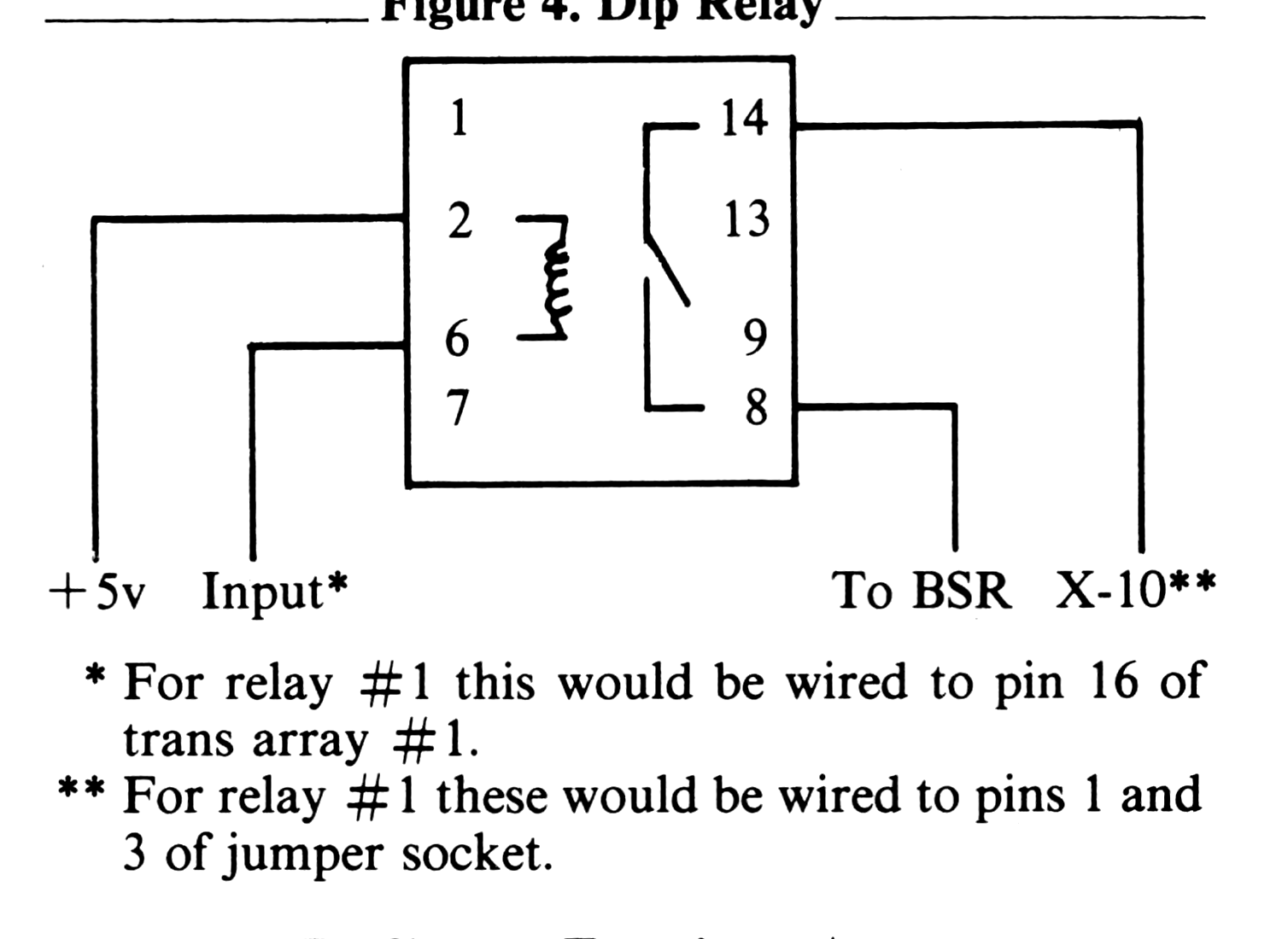
* For relay #1 this would be wired to pin 16 of trans array #1
** For relay #1 these would be wired to pins 1 and 3 of jumper socket.
The newer version of the CC expansion board comes with the decoder circuit built into the board, but the expansion pad pinout has been reversed so that the Zodex board can no longer be plugged directly onto the CC board. The Zodex board can be plugged onto the bus connection for the 16K RAM, but then you have to work out another location for the RAM.
The easiest way to tell the two versions of the CC board apart is that the newer version has a 74LS27 IC chip located next to the optional LM323 voltage regulator while the older version does not.
If you have the older version, you can plug the Zodex board directly onto an edge connector on the C board. Although there are several ways to install the required decoder circuit, I recommend writing to Computer Continuum for a copy of the documentation for the new version. Figure 1, schematic, and Figure 2, legend, are all you will need. Then install the 74LS27 just as it is on the new version. It can be installed in the same spot as the new version with an IC socket, a few jumper wires, and some cuts in the circuit board foil. This will give you essentially the newer version.
If you have the new version of the Computer Continuum board, the decoder is already installed. If you do not want to solder the Zodex board(s) directly together, you will have to build an intermediate connector. The pinouts of the .1 inch center edge connectors are jumpered to the correct fingers of the .156 inch center, 4 x 5 inch PC board.
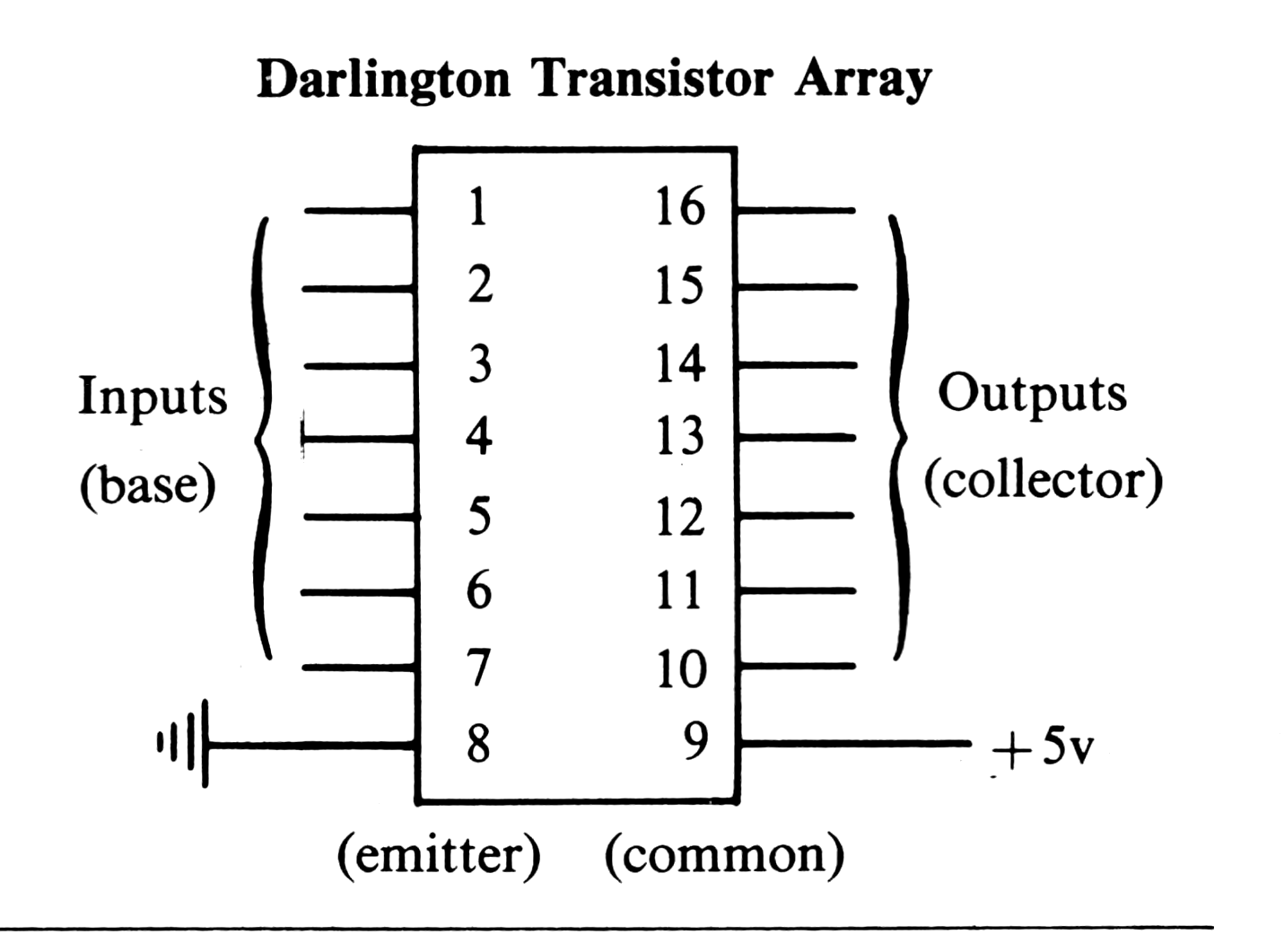
The circuit I will describe uses the RX81 board to drive a Darlington transistor array, activating 5 volt 14 pin DIP relays which in turn switch the BSR X-10. The transistor array and DIP relay pinouts are shown in Figure 4.
As with the robot circuit I plugged the RX81 boards into the Computer Continuum expansion board, and will not repeat the description of that hookup here.
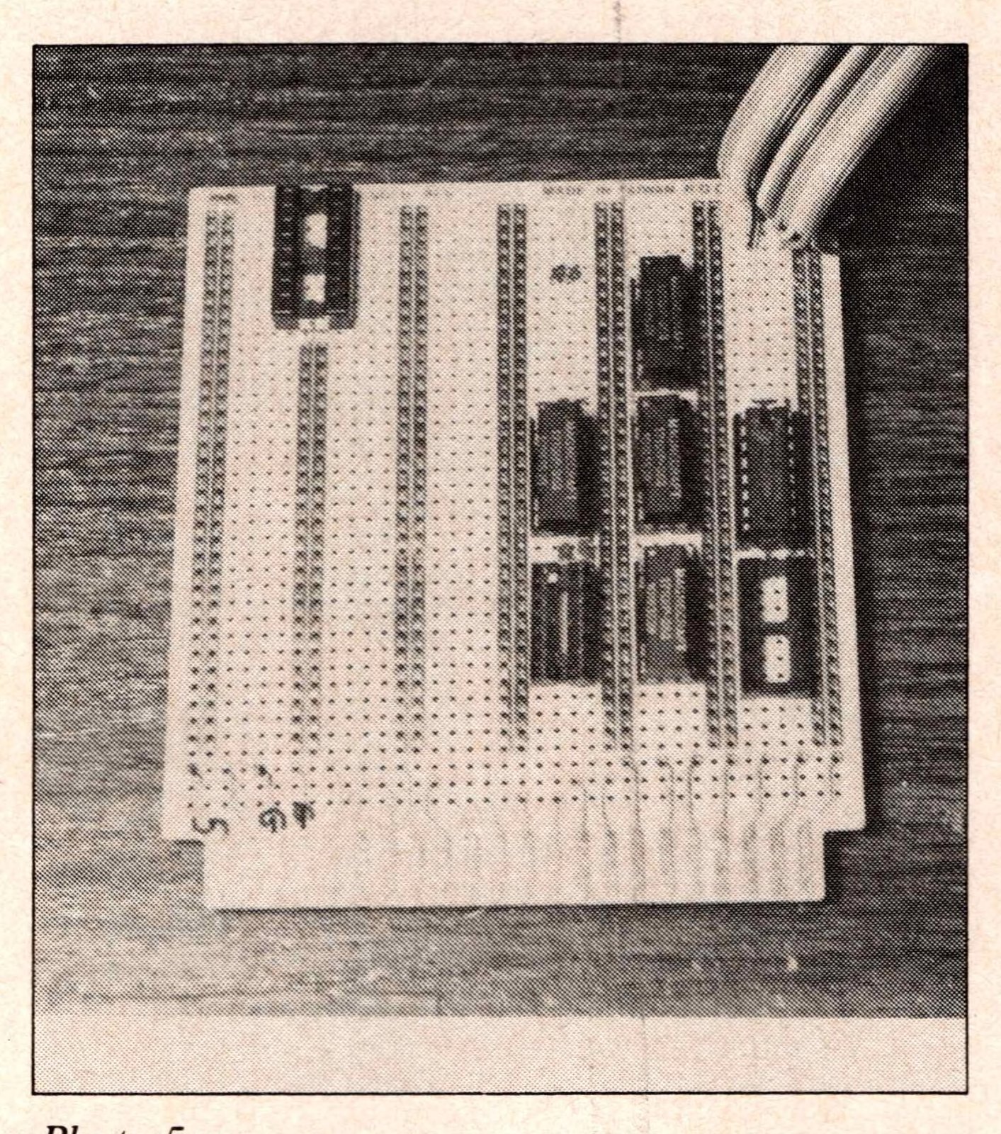
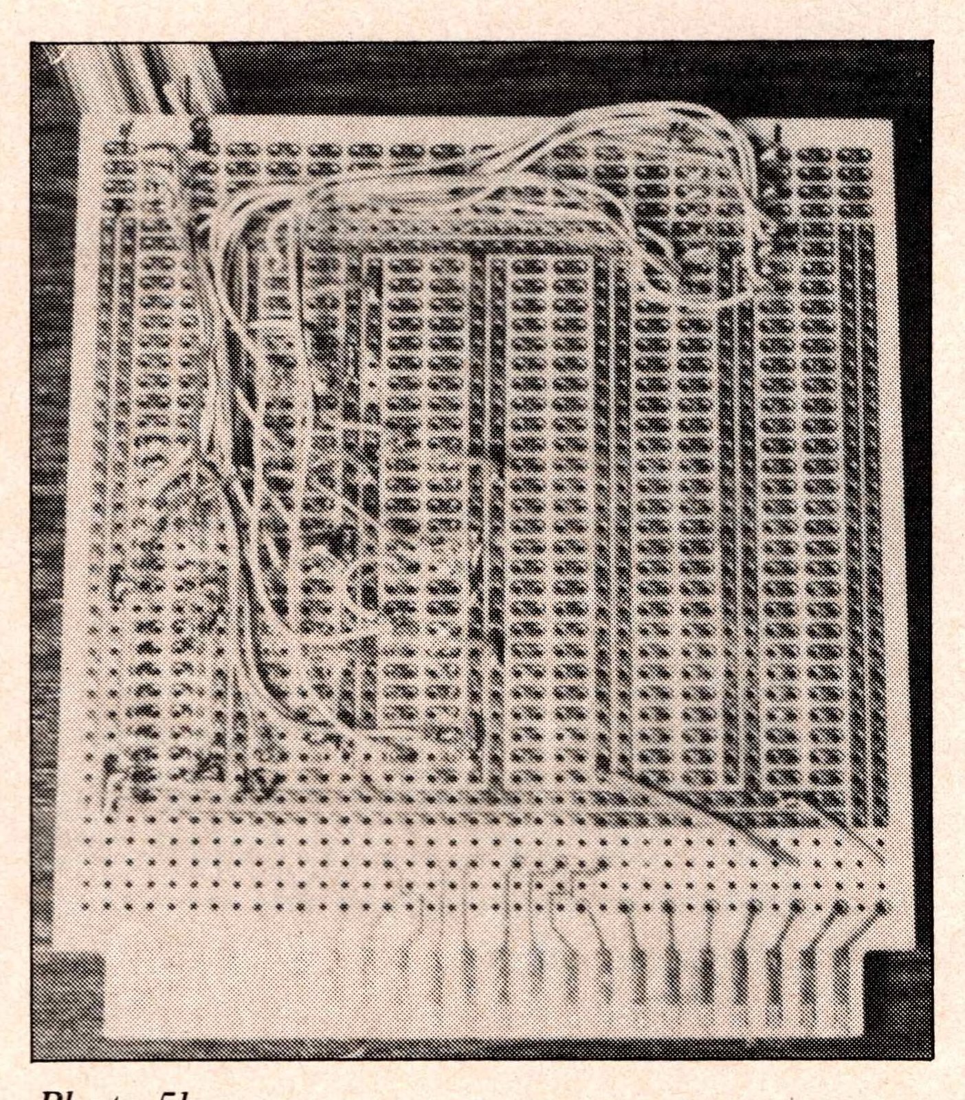
The only additional PC board for this project is pictured in Photo 5. Again I used the OK Hobby Board and plugged it into the Computer Continuum board with electrical interconnection only for +5 volts and ground. The photo shows a partial wire-up with the transistor array at the upper right (the socket below it is for a second transistor array); five adjacent DIP relay sockets (relays are installed only in four); and, the 16 pin DIP socket at the upper left is the output to the X-10. The flat cable in the upper right corner is a jumper from the RX81 output. A complete pinout for the project is listed in Figure 5.
Walking through One Circuit
For an example of the end-to-end wiring of the project, I will walk you through one control circuit. RX81 output D1 (referred to as 1-1) is connected to pin #2 of transistor array #1. The corresponding output of the array is pin #15. This is connected to pin #6 of relay #2. Pin #8 of relay #2 is connected to pin #6 of the DIP jumper socket. In order to complete the switch action of the relay contacts, pin #14 of the same relay is connected to pin #8 of the DIP jumper socket. This line controls the “ON” switch of the X-10.
Remember that ground and +5 volt connections also have to be made to each transistor array and relay (Figure 4). The +5 volts is connected to pin 2 of each relay and pin 9 of each transistor array. Also, a ground connection is made to pin 8 of the transistor array. Note that the ground connection to the coil of each relay is made by the output of the transistor array.
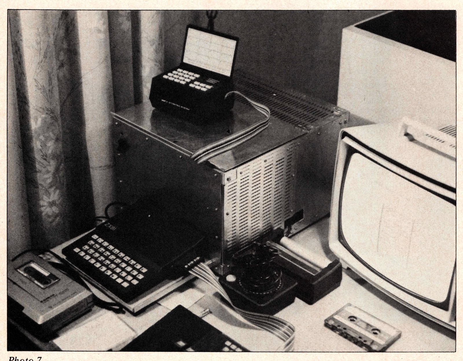
After all wiring is complete, the relay board is connected to the BSR X-10 with a 16 pin double male ended DIP jumper cable (see Photo 6). The RX81 boards and Computer Continuum board are also visable in the photo. My entire computer setup with BSR X-10 sitting on top of the case housing the expansion board is pictured in Photo 7.
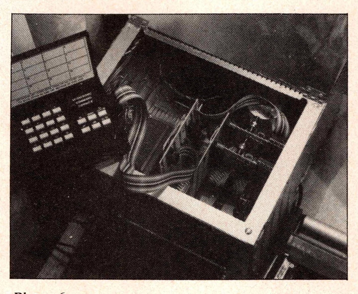
Figure 5.
          Darlington                     DIP Relays
          Transistor
          Arrays*                Pin 8     Pin 14
RX-81                            Input     to DIP    to DIP     Controls
Output                           to Pin    Jumper    Jumper     Switch
          Trans    Input  Output 6 of      Socket    Socket
D0-6      Array #  Pin #  Pin #  Relay #   Pin #     Pin #
1-1       1        1      16     1         1         3          1
1-2       1        2      15     2         6         8          ON
1-3       1        3      14     3         8         10         OFF
1-4       1        4      13     4         5         8          BRIGHT
1-5       1        5      12     5         8         9          DIM
1-6       1        6      11     6         4         8          ALL LIGHTS ON
1-7       1        7      10     7         7         8          ALL OFF
2-1       2        1      16     8         3         11         2
2-2       2        2      15     9         1         6          3
2-3       2        3      14     10        6         11         4
2-4       2        4      13     11        1         4          5
2-5       2        5      12     12        4         11         6
2-6       2        6      11     13        1         5          7
2-7       2        7      10     14        5         11         8

RX-81 output board #1 wired as "out 7"
RX-81 output board #2 wired as "out 6"

Example: Output D0 from board wired as "out 7" is listed above as 1-1

*ULN2003A
Figure 6. Software Commands.
Function/Switch   Relay   Output   POKE A,   POKE B,   Keyboard Entry
1                 1       1-1      1         7         1
ON                2       1-2      2         7         0
OFF               3       1-3      4         7         F
BRIGHT            4       1-4      8         7         B
DIM               5       1-5      16        7         D
ALL LIGHTS ON     6       1-6      32        7         L
ALL OFF           7       1-7      64        7         A
2                 8       2-1      1         6         2
3                 9       2-2      2         6         3
4                 10      2-3      4         6         4
5                 11      2-4      8         6         5
6                 12      2-5      16        6         6
7                 13      2-6      32        6         7
8                 14      2-7      64        6         8

(Note: A=16522 and B=16524)
Start Controlling
Now that the system is wired up, it is time to punch up some programs and start controlling. The data sheet that comes with the RX81 explains a few programming instructions to get you started, but we need to show off the controlling capabilities with a sample program such as in Listing 1 and Listing 2.
Both programs start with the line of machine language in the REM statement followed by POKE 16517, 79.
To activate an output line you first POKE the binary number for the line, then POKE the number of the output board (if you have more than one board) and the activate the command with an OUT USR statement. For example, if you wanted to activate output line #3 on an output board wired as “OUT 7” you would write the program as follows:
100 POKE 16522,4(addresses line #3)
110 POKE 16524,7(addresses board wired as OUT 7)
120 LET OUT=USR 16521(activates command)
Figure 6 summarizes the software commands. In this application you POKE a command which latches a switch on, pause a short time to activate the X-10 function/switch to a key on the ZX/TS keyboard as listed in Figure 6. To turn on appliance or lamp module “1” you first press 1 on the keyboard and then 0. To turn all lamp modules on press A.
Of course, you can work out other control programs. You are limited only by your imagination.
Parts List
BSR X-10 Control System:
Heathkit #GDP-1510
Lamp Module:
Heathkit #GDP-1512
Appliance Module:
Heathkit #GDP-1514
ULN2003 Transistor Darlington Array:
Mouser #511-L203B
Magnacraft 5 colt DIP Relays:
Knapco #171DIP262
16 Pin Single Ended DIP Jumper:
Digi-key #R112-6
16 Pin Double Ended Dip Jumper:
Digi-key #R116-18
PC Board. Hobby Board.
Digi-key #K160-ND
Edgeboard connectors.
Digi-key #C1-22
Digi-key #C5-50
Computer Continuum expansion board
Zodex RX-81
Listing 1.
  2 REM <=[graphic]J [graphic] TAN Y PEEK [graphic]TAN
 10 POKE 16517,79
 20 LET A=16522
 30 LET B=16524
 40 LET C=16521
 50 POKE A,1
 60 POKE B,6
 70 LET OUT=USR C
 80 STOP
 90 GOSUB 530
100 STOP
110 POKE A,2
120 POKE B,6
130 LET OUT=USR C
140 STOP
150 GOSUB 530
160 STOP
170 POKE A,4
180 POKE B,6
190 LET OUT=USR C
200 STOP
210 GOSUB 530
220 STOP
230 POKE A,8
240 POKE B,6
250 LET OUT=USR C
260 STOP
270 GOSUB 530
280 STOP
290 POKE A,16
300 POKE B,7
310 LET OUT=USR C
320 STOP
330 GOSUB 570
340 STOP
350 POKE A,32
360 POKE B,7
370 LET OUT=USR C
380 STOP
390 GOSUB 570
400 STOP
410 POKE A,64
420 POKE B,7
430 LET OUT=USR C
440 STOP
450 GOSUB 570
460 STOP
470 POKE A,128
480 POKE B,7
490 LET OUT=USR C
500 STOP
510 GOSUB 570
520 STOP
530 POKE A,0
540 POKE B,6
550 LET OUT=USR C
560 RETURN
570 POKE A,0
580 POKE B,7
590 LET OUT=USR C
600 RETURN
Listing 2.
   2 REM <=[graphic]J [graphic] TAN Y PEEK [graphic]TAN
  10 POKE 16517,79
  20 GOTO 2060
  30 POKE A,0
  40 POKE B,7
  50 LET OUT=USR C
  60 PAUSE 30
  70 POKE A,10
  80 GOSUB E
  90 PAUSE 70
 100 GOSUB D
 110 IF RND<.5 THEN GOTO 140
 120 POKE A,6
 130 GOTO 135
 140 POKE A,9
 150 GOSUB E
 160 PAUSE 37
 170 GOSUB D
 180 GOTO 2210
 190 POKE A,0
 200 LET OUT=USR C
 210 PAUSE 30
 220 RETURN
 230 LET OUT=USR C
 240 RETURN
 250 POKE A,0
 260 POKE B,7
 270 LET OUT=USR C
 280 PAUSE 30
 290 POKE A,10
 300 GOSUB E
 310 PAUSE 37
 320 GOSUB D
 330 POKE A,9
 340 GOSUB E
 350 PAUSE 5
 360 GOSUB D
 370 GOTO 2210
 380 POKE A,0
 390 POKE B,7
 400 LET OUT=USR C
 410 PAUSE 30
 420 POKE A,10
 430 GOSUB E
 440 PAUSE 37
 450 GOSUB D
 460 POKE A,6
 470 GOSUB E
 480 PAUSE 5
 490 GOSUB D
 500 GOTO 2210
 510 STOP
 520 REM RANDOM SELECT
 530 IF RND<.67 THEN GOTO 2250
 540 POKE A,0
 550 POKE B,7
 560 GOSUB E
 570 POKE A,10
 580 GOSUB E
 590 PAUSE 100
 600 POKE A,0
 610 GOSUB E
 620 POKE A,9
 630 GOSUB E
 640 PAUSE 37
 650 POKE A,0
 660 GOSUB E
 670 POKE A,5
 680 GOSUB G
 690 FOR W=1 TO 12
 700 LET IN=USR F
 710 IF IN=4 THEN GOTO 760
 720 IF IN=1 THEN GOTO 760
 730 IF IN=5 THEN GOTO 760
 740 IF W=12 THEN GOTO 780
 750 NEXT W
 760 GOSUB D
 770 GOTO 380
 780 GOSUB D
 790 POKE A,10
 800 GOSUB G
 810 FOR W=1 TO 20
 820 IF W=20 THEN GOTO 840
 830 NEXT W
 840 GOSUB D
 850 POKE A,6
 860 GOSUB E
 870 PAUSE 90
 880 POKE A,0
 890 GOSUB E
 900 POKE A,5
 910 GOSUB G
 920 FOR W=1 TO 12
 930 LET IN=USR F
 940 IF IN=2 THEN GOTO 990
 950 IF IN=1 THEN GOTO 990
 960 IF IN=3 THEN GOTO 990
 970 IF W=12 THEN GOTO 1010
 980 NEXT W
 990 GOSUB D
1000 GOTO 250
1010 GOSUB D
1020 POKE A,10
1030 GOSUB G
1040 FOR W=1 TO 18
1050 IF W=18 THEN GOTO 1070
1060 NEXT W
1070 GOSUB D
1080 POKE A,9
1090 GOSUB E
1100 PAUSE 37
1110 POKE A,0
1120 POKE B,7
1130 GOSUB E
1140 POKE A,32
1150 POKE B,7
1160 GOSUB G
1170 PAUSE 80
1180 GOSUB D
1190 POKE A,16
1200 GOSUB E
1210 PAUSE 130
1220 GOSUB D
1230 POKE A,32
1240 GOSUB E
1250 PAUSE 45
1260 GOSUB D
1270 POKE A,144
1280 GOSUB E
1290 POKE A,18
1300 GOSUB G
1310 PAUSE 30
1320 POKE A,154
1330 GOSUB E
1340 PAUSE 20
1350 GOSUB D
1360 POKE A,128
1370 POKE B,7
1380 GOSUB E
1390 PAUSE 70
1400 GOSUB D
1410 FOR W=1 TO 300
1420 LET IN=USR F
1430 IF IN=128 THEN GOTO 1460
1440 IF W=300 THEN GOTO 1460
1450 NEXT W
1460 POKE A,64
1470 POKE B,7
1480 GOSUB E
1490 POKE A,96
1500 POKE B,6
1510 GOSUB E
1520 PAUSE 50
1530 POKE A,33
1540 GOSUB G
1550 PAUSE 10
1560 POKE A,97
1570 GOSUB E
1580 PAUSE 5
1590 GOSUB D
1600 POKE A,70
1610 POKE B,7
1620 GOSUB G
1630 PAUSE 220
1640 POKE A,64
1650 GOSUB E
1660 POKE A,69
1670 GOSUB G
1680 PAUSE 280
1690 POKE A,64
1700 GOSUB E
1710 POKE A,144
1720 POKE B,6
1730 GOSUB E
1740 POKE A,18
1750 GOSUB G
1760 PAUSE 10
1770 POKE A,146
1780 GOSUB E
1790 PAUSE 20
1800 GOSUB D
1810 LET IN=USR F
1820 IF IN=0 THEN GOTO 1840
1830 PAUSE 400
1840 POKE A,128
1850 POKE B,7
1860 GOSUB E
1870 POKE A,96
1880 POKE B,6
1890 GOSUB E
1900 PAUSE 100
1910 POKE A,33
1920 GOSUB G
1930 PAUSE 10
1940 POKE A,101
1950 GOSUB E
1960 GOSUB D
1970 POKE A,64
1980 POKE B,7
1990 GOSUB E
2000 PAUSE 40
2010 POKE A,6
2020 GOSUB G
2030 PAUSE 230
2040 GOSUB D
2050 GOTO 2210
2060 LET A=16522
2070 LET B=16524
2080 LET C=16521
2090 LET D=190
2100 LET E=200
2110 LET F=16514
2120 LET G=230
2130 POKE A,0
2140 POKE B,7
2150 LET OUT=USR C
2160 POKE A,0
2170 POKE B,6
2180 LET OUT=USR C
2190 PAUSE 400
2200 LET RN=1
2210 POKE A,5
2220 POKE B,7
2230 LET OUT=USR C
2240 LET TN=0
2250 LET TN=TN+1
2260 LET IN=USR F
2270 IF IN=1 THEN GOTO 30
2280 IF IN=2 THEN GOTO 250
2290 IF IN=4 THEN GOTO 380
2300 IF IN=3 THEN GOTO 250
2310 IF IN=5 THEN GOTO 380
2320 IF IN=7 THEN GOTO 30
2330 IF TN=20 THEN GOTO 530
2340 GOTO 2250
Addresses:
Heathkit, Heath Co., Benton Harbor, MI 49022
Mouser Electronics, 11433 Woodside Ave., Santee, CA 92071
Knapp of Florida, Inc., 4750 96th St. N., St. Petersburg, FL 33708
Digi-key Corp., PO Box 677, Thief River Falls, MN 56701
Computer Continuum, 301-16 Ave., San Francisco, CA 94118
Zodex, East Hill, Oakham, MA 01068