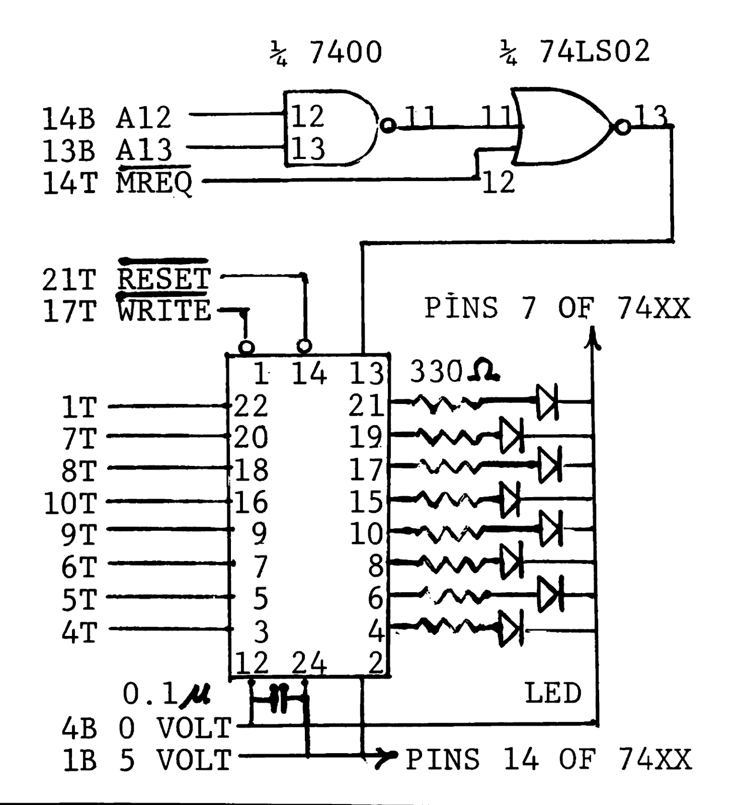
Your ZX80 or MicroAce can talk to other machines if you wire and program a simple output port. The port latches any 8-bit data byte output from the data bus and is internally buffered. You can sink up to 15 mA per line to drive LED’s or relay coils (to access appliances). You can also (as this project does) source up to 15 mA per line. This device typifies memory-mapped I/O, the building block to connect other add-ons.
You talk to your interface via software using the BASIC POKE function. It is completely reset on system power-up. The location 12288(decimal)=3000H addresses the port device. POKE the data to location 12288 each time you want to change the output. Then your program can perform additional, unrelated tasks while the latch remembers your previous order.
The program listed sequences through 8 LED’s at a rate you select. Repeating displays give a moving effect like a theatre sign. With minor software changes, you may sweep it in either direction and any format. Modify the delay between each LED being gated-on (and thus the rate of motion) by altering line 120. For example, decrease the FOR-TO number to 25 for a faster display.
This scheme works by making the I/O chip look like a memory location. For this output-only device, you can use a ROM address because the ZX80 never writes to a ROM address for any other purpose. I/O ports need empty addresses.
Decoder logic generates the address from A13 “ANDed” with A12 and M̅R̅E̅Q̅ to select the 8212 I/O chip. Since the address is not fully decoded, the port responds to every address between 3000H and 3FFFH. Data clocked-in via the W̅R̅ pulse is latched to the outports on the rising edge of W̅R̅.
The connector on the rear of the ZX80 chassis provides access. The +5 Volt, on-board, regulated supply operates your port device. A 7400 quad 2-input NAND gate and the 74LS02 quad 2-input NOR gate decode the address 12288.
Two operating modes are possible with the 8212. As shown, you have an output port to take signals from the ZX80 to the world outside. But, wired and addresses differently, the 8212 could take data from outside your ZX80 and make it available to the computer for processing or display. For more info on other connections see Adam Osborne’s Introduction to Microcomputers, Volume II, June 1977 revision, pp 4-122 to 4-131.
Project parts are readily available from electronics suppliers listed in the back of electronics hobby magazines. One supplier is Jameco Electronics, 1021 Howard Ave., San Carlos, CA, 94070, (415)592-8097. Prices: $3.25 for the 8212 I/O IC, 29¢ for a TTL IC. Any type or color LED (about 20¢ each) is OK.
In the diagram (p.8) 14B means pin 14, bottom side, of the ZX80 connector; 14T means pin 14, top side. Count pins from left to right with keyboard toward you and readable. On the board, pin 23T is labeled 23A.
  10 REM * EXAMPLE OF MEMORY-MAPPED OUTPUT *
  20 REM * USING AN INTEL 8212 PARALLEL INPUT/OUTPUT DEVICE. *
  40 REM * DELAY LOOP AT STATEMENTS 120 AND 130. *
  50 REM * CONTROLS THE STROBE/MULTIPLEXER RATE. *
  60 LET N=0
  70 LET D=2**N
  80 LET N=N+1
  90 POKE 12288,D
 100 LET A=128-D
 120 FOR I=1 TO 100
 130 NEXT I
 140 IF A=0 THEN GO TO 60
 150 GO TO 70
 160 REM * 12288=ADDRESS (3000H)
 170 REM OF I/O PORT (8212)
 180 REM * PROGRAM CONTINUES*
 190 REM * UNTIL "BREAK" IS *
 200 REM * DEPRESSED. *
 210 STOP