Authors
Publication
Pub Details
Date
Pages
WARNING: Modification requires opening the computer case, drilling one hole and cutting out a opening the slot for a will void any warranty from the manufacturer.
Parts Required
- 1 9 pin *D° connector, female (same as JOY STICK connector).
- 1 small N/0 (“normally open”) push button switch for RESET.
- 2 4-40 x 1/2 inch bolts and nuts to secure connector.
- 2 feet of plastic insulated hook-up wire.
Tools Required
- Sharp knife (X-ACTO type) .
- Soldering iron and solder.
- Small file.
- Drill bits and drill (holes for bolts and N/0 push switch).
- Phillips screw driver.
Modification – Mechanical
Place the T/S 2068 on a flat surface which is covered with a towel or foam, on the keyboard side.
Remove each of the seven (7) Phillips head screws.
Turn the case over on the back and carefully pry the case apart.
Hold the keyboard section at a right angle to section the bottom and remove three (3) Phillips screws securing the PC assembly to the case bottom.
With a pencil, mark the section on the inside case, back of the case, the span between the “MONITOR” jack and assembly (#335-80006). This is the small approximately two (2) inches. Set aside the keyboard section of the assembly.
Using the the template provided, slowly and carefully cut into the case around the outline for the “D” connector. This will require repeat cutting.
Fit the female “D” connector into the opening from the outside of the case. If the opening is too tight, use a file to enlarge it. Drill both holes for the bolts and secure the connector to the case with the 4-40 bolts and nuts.
Drill a hole for the N/O push switch.
Insert the switch into the hole previously drilled and secure with the hardware provided on the switch.
Modification – Electrical
Place the PC assembly into the bottom case. Do not secure with screws at this time. Prop up the keyboard section with a pencil.
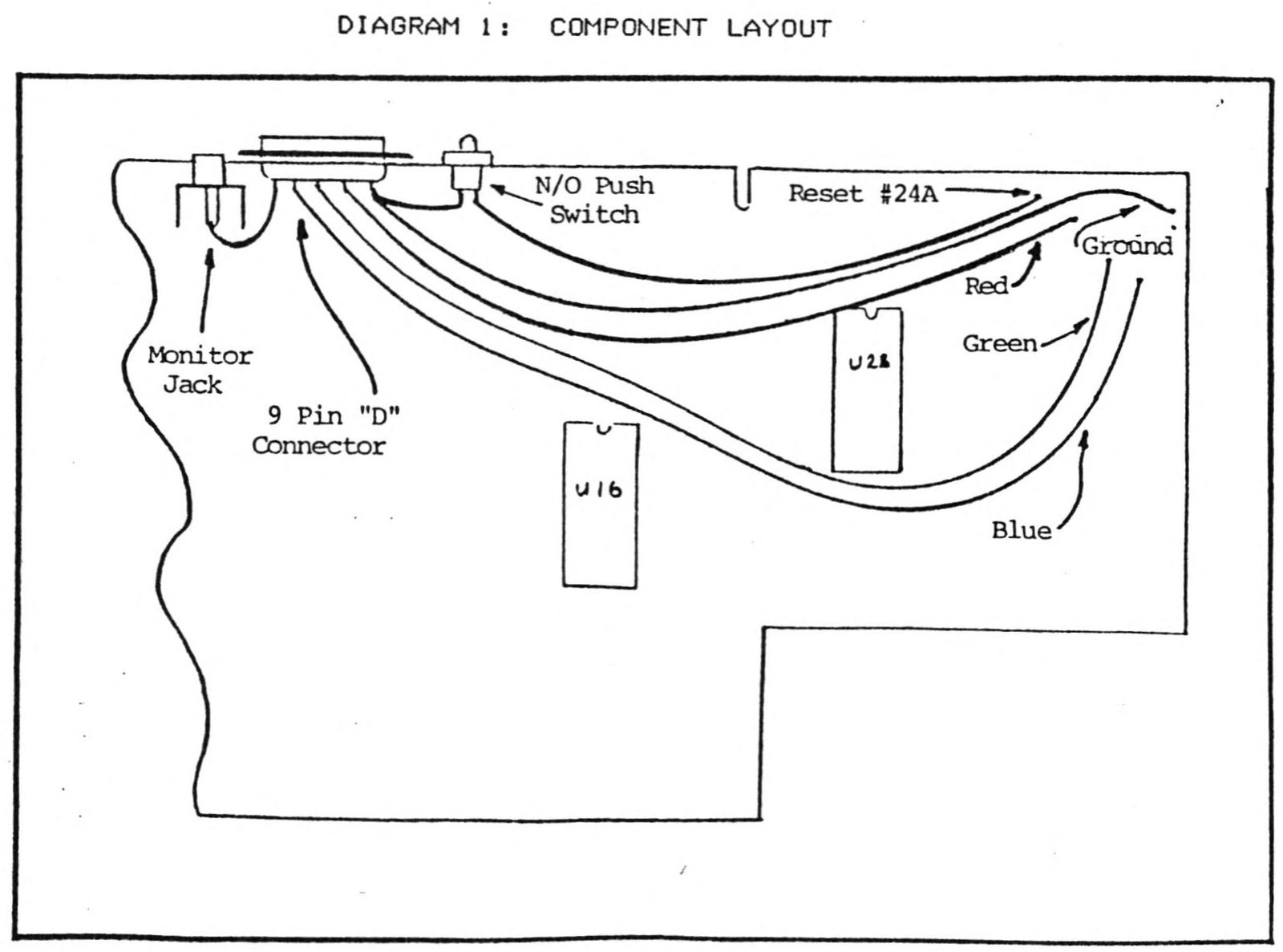
Cut a short length of wire to connect to the lug of the push switch with the “D” connector which is closest to the switch. Solder the wire to the push switch ONLY.
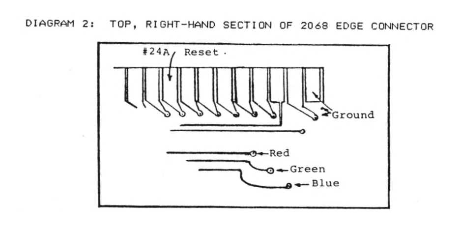
Locate the GROUND (2 plated through holes) on the computer edge connector. This is at the far right-hand side of the edge connector.
Cut a length of wire to connect the GROUND at the edge connector with the same “D” connector terminal that the shor wire will connect to from the push switch.
Solder both wires to the terminal connector and to a ground plated through hole.
From the GROUND terminal on the 20658 edge connector, locate the 9th terminal (#24A). This is RESET.
Cut a length of wire from the plated through hole which connects to the RESET terminal to the free lug of the push switch. Solder the wire in place.
Locate the three (3) plated through holes, which are located just below the edge connector at the far right of the PC assembly. These contacts are “RGB” respectively.
The upper hole is Red; the center hole is Green; the lower hole is Blue.
Measure and cut three (3) lengths of wire to connect the RGB plated through holes to three terminals on the edge connector, then solder these wires in place.
Measure a short length of wire from the connector to the center contact of the computer MONITOR jack (This connection provides a SYNC signal to the RGB monitor).
Solder the wire in place.
Carefully inspect all of your solder connections to insure that they do not have shorts and/or solder bridges. When satisfied that everything is OK, replace the three (3) screws securing the PC assembly to the case bottom.
Carefully re-assemble the computer case with the seven (7) Phillips head screws previously set aside.
Checkout
A mating connector from the 9 pin “D” connector is required for RGB checkout. The cable detailed in last month’s article (External RGB Modification) can be used if the cable ends are removed from that assembly and soldered to a male “D” connector.
Power up the monitor and computer. If all is well, the copyright message should appear on the screen. If a problem exists, re-check all connections previously made.
Press the RESET button. The screen will clear, then display the black box and then the copyright message.
Key in the following short program, “COLOR BARS”.
 10 FOR b=1 TO 22: FOR p=7 TO 0 STEP -1
 20 PAPER p: PRINT "    ";
 30 NEXT p: NEXT b
Behold the beautiful sharp image on the monitor screen that can only be possible with RGB.
Image Gallery