ESC Escape control code circuit
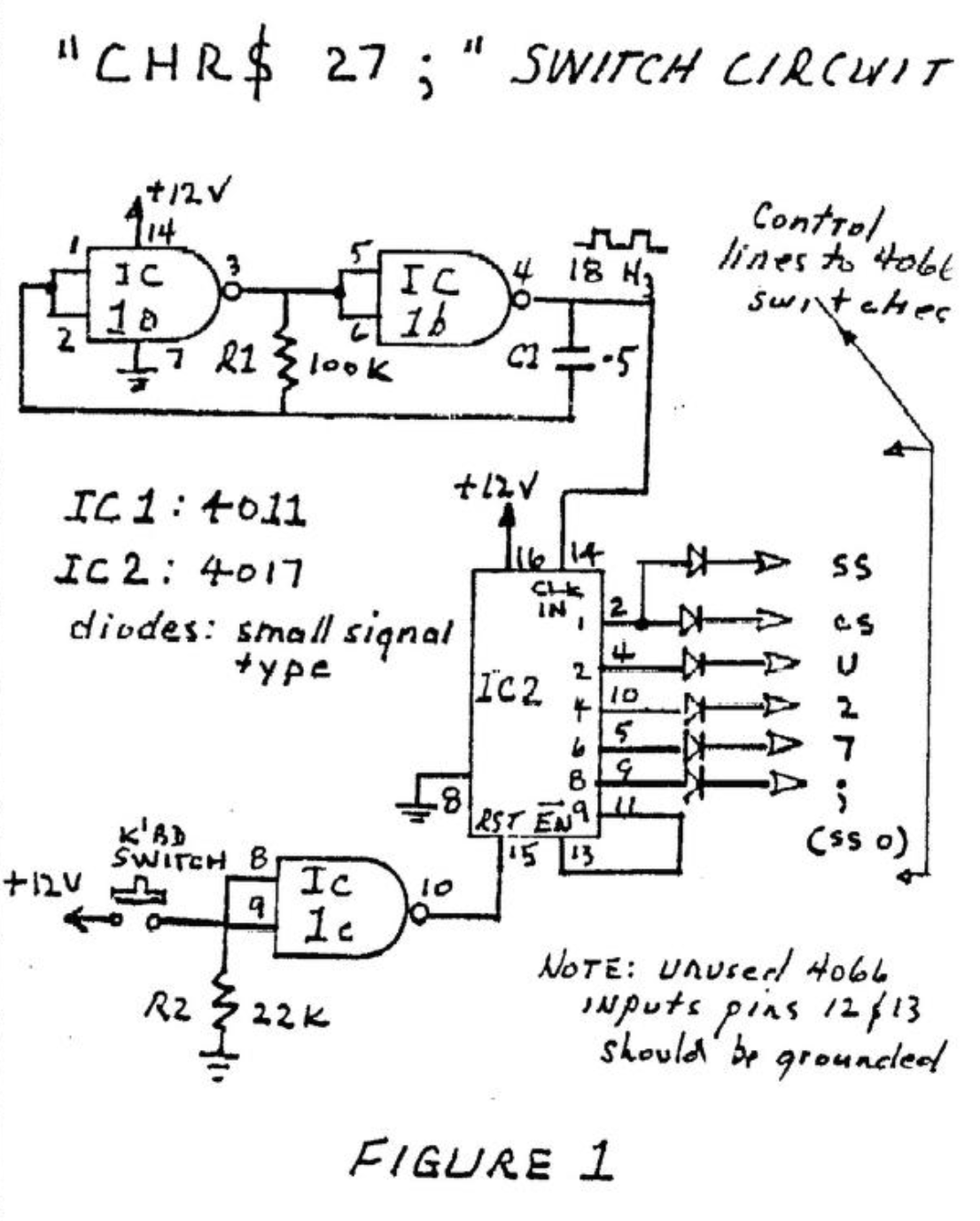
If you have a full-sized printer you might appreciate this circuit which generates the series of characters for the ESC escape control code – CHR$27; – with one keystroke. The circuit can be implemented if you use 4066’s to interface the keyboard with the computer.
Here’s how Figure 1 works. Two NAND gates form an 18Hz clock. This is as fast as the computer can digest if you have more than three lines in the PRINT statement. The 18 Hz wavetrain is feed to the clock input of a 4017 counter. The 4017 has 10 decoded outputs – 0 through 9. When the computer is fired up, the 4017 counts UP to 9 before the computer has completed its startup routine. When output 9 goes high, the counter is disabled. When the keyboard switch is depressed, a NAND gate used as an inverter resets the counter to zero thus enabling it to count again. As it counts back up to 9 the appropriates keyboard lines are switched in sequence through the 4066s.
Power for this little circuit and the 4066s was taken from the output pin of the UA78L12 regulator on the computer board. It’s the little one, near the big electrolytic capacitors that looks like a transistor. If your 4066s are powered from 5v at present, be sure to change to the 12v supply. Its a good idea anyway – the higher supply voltage gives better noise immunity and allows you to use two diodes in series in the switching logic lines if you want to.
“Special Keys”
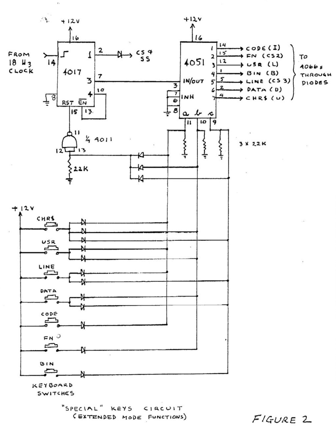
Figure 2 shows how seven Extended Mode functions can be reached with single keystrokes by using another 4017 and a 4051. The 18 Hz wavetrain is fed into the input of the 4017 counter. Output 1 is connected to the caps and symbol shift control lines of the 4066s. Output 3 is connected to the IN/OUT pin of the 4051. This chip is technically called “muitipiexer/demultiplexer” but it is reaily just a single pole, 8 position switch. Pin 3 (IN/OUT) is connected to one of 8 OUT/IN pins numbered 0 to 7 according to the state of the three control inputs a, b, and c (a is the least significant bit). The keyboard switches are encoded with diodes. The respective OUT/IN pins are connected to the appropriate 4066 control lines. Any one of the 4051 control inputs going high resets the counter to zero and thus starts the count sequence, stopping when it gets to 4.
Image Gallery