
Authors
Publication
Pub Details
Date
Pages
Your 2068 uses ports to scan its keyboard, as do all Sinclairs. Each uses the same addresses, but the data differs.
As you know, Sinclair uses the CPU to scan its matrix keyboard. Forty keys, arranged as 8 half-rows of 5 keys each, provide all the functions. Additional keys simply connect parallel to a primary key.
From the ZX/TS schematic, we know that the 5 lines KBD0–KBD4 connect vertical columns of keys——0 connecting SHIFT, A, Q, 1, 0, P, ENTER, and SPACE; 4 connecting V, G, T, 5, 6, Y, H, and B. You’ll find this pattern from Z to SYMBOL SHIFT, X to M, and C to N.
Each half-row connects to one ADDRESS line of the CPU. As you see in Figure 1, the half-row connects to A8–A15 (via a diode).
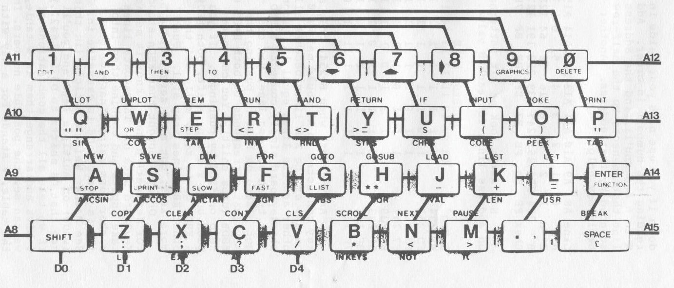
When Z80 processors execute a port command——IN or OUT——the lines A8–A15 contain a number from one of the registers. The instruction IN r,(C) reads the port number held in C, places the data read in r, and puts register B on address lines A8–A15 during the read (see p. 254 of the Zilog programming manual). If r stands for register A, this assembles to ED, 78 (237, 120 dec.)——just what you find in the Spectrum at 0296H (662 dec.). C contains the port address FE (254). By using LD BC,portadd followed by IN A,(C) we can specify portadd as the 16 bit number to place on the address bus during a port read. Effectively, we get 16 bit port addresses. Now let’s arrange the data from the Spectrum manual.
BC Register     Scanned      BC Register
Hex   Dec     n Keys  Keys n Dec    Hex
F7FE  63486   3 1-5    0-6  4 61438 EFFE
FBFE  64510   2 Q-T    P-Y  5 57342 DFFE
FDFE  65022   1 A-G   EN-H  6 49150 BFFE
FEFE  65278   0 CS-V  SP-B  7 32766 7FFE
Note that register C always holds FE, port 254, to read the keyboard. Register B sequences down if you use n as your guide in reading the numbers in order. Add 8 to n and you’ll find the address line that connects to the half-row scanned by that address. Another table may help.
Line A8  A9  A10 A11 A12 A13 A14 A15
n     0   1   2   3   4   5   6   7
2**n  1   2   4   8  16  32  64 128
B   254 253 251 247 239 223 191 127
Bhex FE  FD  FB  F7  EF  DF  BF  7F
Now let’s look at bit patterns on address lines for each B value.
                  ADDRESS LINE
B Reg      08 09 10 11 12 13 14 15
FE 254      0  1  1  1  1  1  1  1
FD 253      1  0  1  1  1  1  1  1
FB 251      1  1  0  1  1  1  1  1
F7 247      1  1  1  0  1  1  1  1
EF 239      1  1  1  1  0  1  1  1
DF 223      1  1  1  1  1  0  1  1
BF 191      1  1  1  1  1  1  0  1
7F 127      1  1  1  1  1  1  1  0
As you see, when B=254, only a key connected to A8 could make a 0 on any of the KBD lines because all other address lines equal 1. Since the keyboard simply connects a KBD line to an address line, you can get a zero on KBD0 by pushing the key that corresponds to both B=FE & KBD0 (caps shift). You can make zero on KBD4 by pushing V. If you push both V & caps shift, both KBD0 & KBD4 go to zero, while all the other KBD lines stay at 1. Push more keys, get more zeros, up to 5.
Once I thought that KBDn stood for KeyBoarD n; now I know it means KeyBoard Data n. Those Data lines take inputs and combine them into number form using binary weights. (D5 is unused; D6 is cassette in. See Mather White’s article on multiple keys and you’ll see that D4 shifts to D5 in 16422.) If we take all the combinations of 5 bits and arrange them in a table, we can see the possible numbers. In the table, # stands for a key with no letter——a SHIFT, SPACE or ENTER.
Number     D0 D1 D2 D3 D4  Keypress
31          1  1  1  1  1  NO KEY
30          0  1  1  1  1  #AQ10P##
29          1  0  1  1  1  ZSW29OL#
27          1  1  0  1  1  XDE38IKM
23          1  1  1  0  1  CFR47UJN
15          1  1  1  1  0  VGT56YHB
Binary Val  1  2  4  8 16
See that if you press no key, all the data bits equal one and the machine sees 31. Pressing one key makes the corresponding bit equal zero and subtracts the binary value from 31 to generate the number in the left column. If you read down any column under the keypress heading, you will recognize a half-row of your computers keyboard. On the right side of the computer, the keys read from right to left, just what you expect when you look at a ZX/TS schematic for the key matrix.
Well, what if you push more than one key? Stay in one half-row and you will generate the remaining numbers. If you push keys in other rows, the keyscan routine will sort them as B takes different values.
Every combination of keys in a half-row generates a unique value. Pressing combinations subtracts the key-values from the no-key value.
Although Sinclair machines do not use this keyboard property, you can see it with a simple program on your 2068. If you enter:
100 PRINT AT 0,0;IN 65022:GO TO 100you can press ASDFG half-row keys in combination and see what values result. Change the argument of IN to 57342 and you move to the POIUY half-row. Try each address shown in the first table of this article. Notice that the value depends only on position in the half-row; half-row selection varies with address.
Now try this. With no key pressed, and the preceding one-line program entered, put a tape in your recorder and play it into the machine. Notice that the number on your screen changes. As bits come in from the EAR jack, D6 goes to 1, and the number jumps to 95 (31 because no key is pressed plus 64 from the D6 line).
Spectrum computers differ slightly in the values returned for keypresses. But the differences are regular and understandable.
Machine   No-Key  D D D D D D D D
Name      Value   0 1 2 3 4 5 6 7
TS1000       63   1 1 1 1 1 1 0 0
TS2068       31   1 1 1 1 1 0 0 0
SPECTRUM    255   1 1 1 1 1 1 1 1
SPECTRUM3   191   1 1 1 1 1 1 0 1
As Robert La Jeunesse pointed out in SYNTAX (Oct.83, p22), you need only use LD BC,portadd plus an IN A,(C) to achieve register indirect addressing on your ZX/TS computer. For convenience, we will also use RAND to convert decimal to hex and store the result in the system variable SEED (16434,5). (A trick we learned from the June 1983 issue of the Sinclair-Timex User Group Newsletter published by The Boston Computer Society.) To get the widest possible application of this, let’s set RAMTOP below 1K and use a routine that can run on a ZX81, but make the machine code run independent of location. This code simulates IN for your ZX/TS.
POKE 16388,236;Set RAMTOP To 17388
POKE 16389,67
NEW
POKE 17388,237;ED LD BC,(nn)
POKE 17389,75 ;4B nn=SEED
POKE 17390,50 ;32 Address of SEED
POKE 17391,64 ;40 sys var (16434)
POKE 17392,237;ED IN r,(C) r=A
POKE 17393,120;78
POKE 17394,6  ;06 LD B,0
POKE 17395,0  ;00
POKE 17396,79 ;4F LD C,A
POKE 17397,201;C9 RETURN TO BASIC
Now use this BASIC loop:
10 INPUT N  (n is a number from our
20 RAND N                first table.)
30 LET X=USR 17388
40 PRINT AT 0,0;N,X
50 GOTO 30
Special thanks to Andy Boles & his users’ group, 2059 Pennel Cove, Memphis, TN 38116, 901/346-0890
Note: Type-in program listings on this website use ZMAKEBAS notation for graphics characters.