Ed.—A WORD OF CAUTION: Any hardware project that involves modifications to your computer must be approached with extreme caution. SYNC cannot be responsible for problems that may arise from attempting hardware projects. Obviously, any damage done to the computer can be costly in time and money for repairs or even replacement.
Introduction
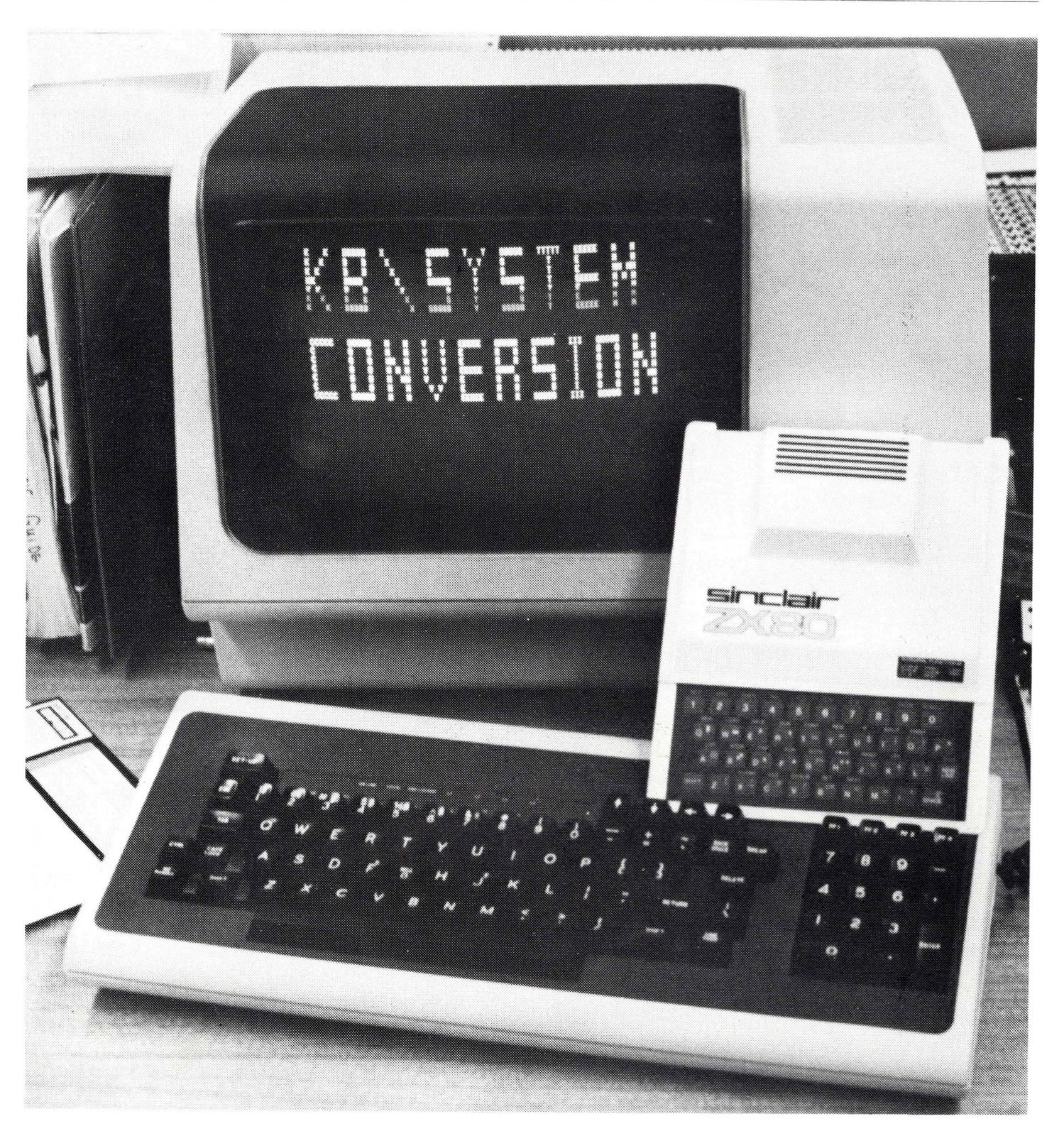
As a daily user of some of Digital Equipment Corporation’s nicest micro-based laboratory computer systems, it is easy for me to be prejudiced about system design and operating convenience. In particular, I will have to admit a real fondness for DEC’s VT-103/LSI-11 ergonomically designed video terminal with detached keyboard and self-contained 16 bit LSI-11 microcomputer bus/backplane.
As a ZX80 owner, on the other hand, I also find system simplicity and portability very attractive. As others have pointed out, one only needs a battery pack, a small portable television, and a ZX80/1 or MicroAce for a backpackable combination that can bring computing to places like the high Sierra Nevada wilderness.
On first thought, it would seem a considerable design problem to configure a system combining DEC-style keyboard convenience and modularity with Sinclair-style portability. As it turns out, the problem is not very great, and the average (read: technically sophisticated) SYNC reader can probably handle it with ease.
The purpose of this article is to review computer keyboard (KB) conversion for the ZX80 or MicroAce and to describe the first phase of an adaptation that retains original system portability while allowing upgrading to an “advanced” expansion-bus oriented system.
Keyboard Conversion Kits
The fundamental conversion described here can be made with almost any KB switch array, 40 keys, new or used, so long as the switches are normally open and are closed with a keystroke. Such keyboards can then be paralleled with the ZX80 keyboard. The Schultz Systems keyboard used in this article was chosen because the kit included the electronics for additional features not available with the standard Sinclair or MicroAce. These features, which include shift-locking, auto-repeat, and single key, auto-upshifted functions (such as single key rubout) will be covered in a future article on advanced conversions. Unfortunately, Schultz no longer provides complete conversion kits with used KB’s, although complete instructions, KB source listing, and other parts can still be obtained. (At this writing kits and instructions are available from L.J.H. Enterprises and Double H Electronics.)
Construction Details
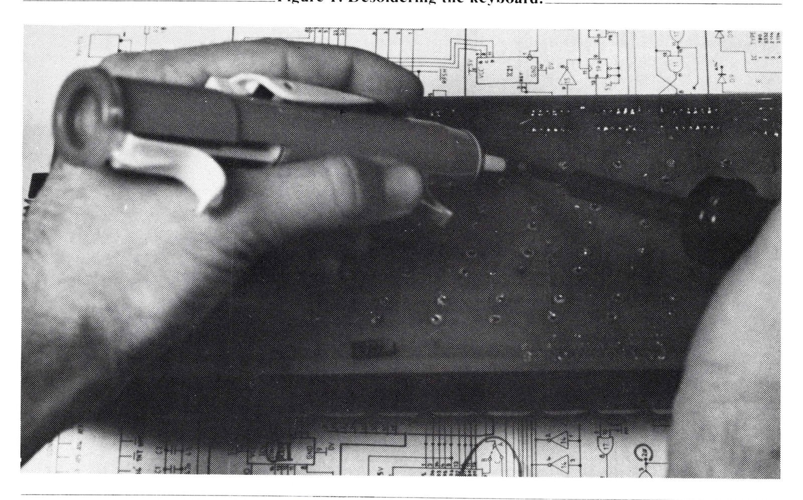
The KB provided, as is probably the case with most used units, came equipped with a printed circuit board electronics matrix attached to the switch terminals. To begin the conversion, it was thus necessary to remove this PC board. A de-soldering tool, such as a SOLDAVAC (TM) (Radio Shack no. 64-2085 or equivalent) is a real necessity. Even with this tool, unsoldering the old matrix board was clearly the most difficult part of the initial conversion, taking about 2 of the 4 hours needed for the project. In order to avoid switch damage on removing the PC board, all of the solder had to be removed from each connection. This required 2 complete passes over the board. (Figure 1)
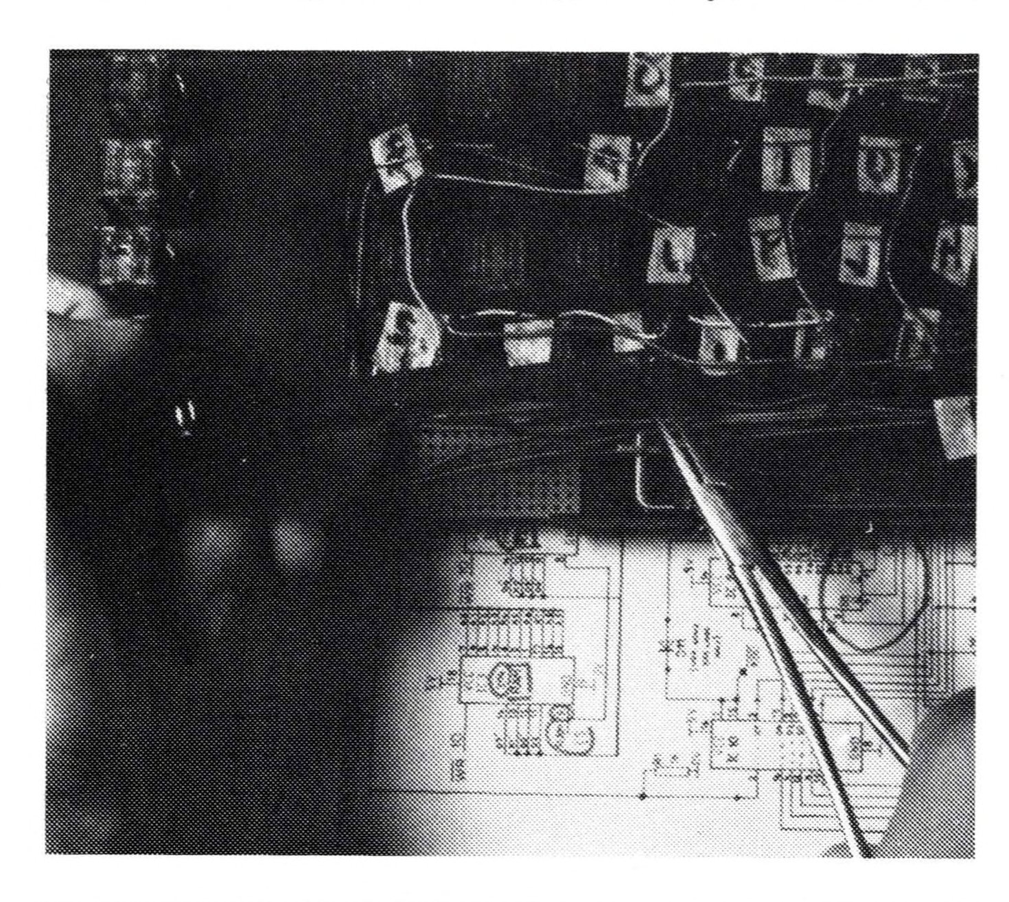
Once removed, the old matrix board was kept for salvageable parts like sockets, IC’s, diodes, resistors, and capacitors—an added bonus! Each switch was tested with an ohmmeter in order to avoid unpleasant surprises and then labelled on the back to aid in wiring. Although it was not necessary with my KB, the circuit board could have been retained for switch support, with each terminal contact being isolated from the old circuit by cutting printed circuit conductors.
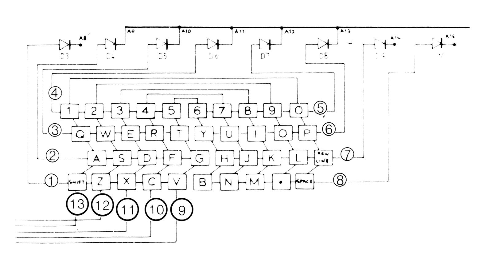
The switches were then strung together in rows and columns using the ZX80 matrix convention (see SYNC 3:42 for greater detail). Briefly, this consists of wiring in parallel one terminal of each switch in 8 rows (e.g., “shift,” Z, X, C, V) and the other terminal of each switch in 5 “folded” columns 9 to 13. Since there were two “shift” keys, each was wired the same to allow shifting with either hand. For convenience, I did the same with adjacent “,” and “.” keys. All connections were made with standard insulated hookup wire. (Figure 2)
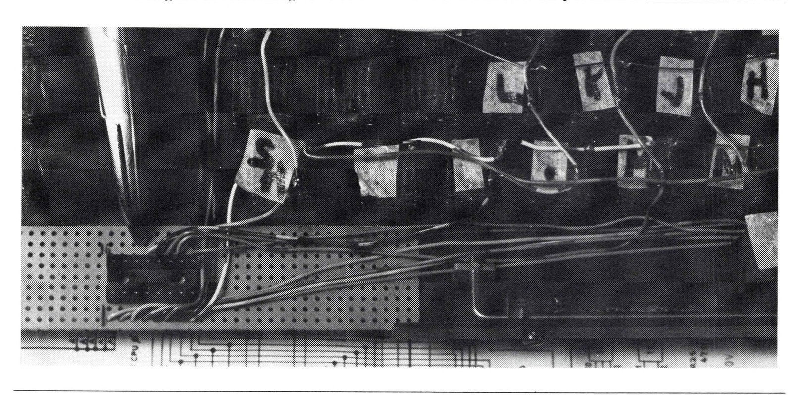
For connecting the wired KB matrix to the computer, I used a 16 pin DIP terminated 18″ ribbon “jumper” cable (Radio Shack 276-1976) and 2 16 pin DIP IC sockets (Radio Shack 276-1998). A small piece of 0.10 spacing “perf-board” was attached to a convenient slot in the KB frame using cyanoacrylate glue (“Crazy glue”). One of the 16 pin IC sockets was glued to the board, and the row/column leads (1-8/9-13) were soldered to its terminals in numerical order (1-8 and 9-13 respectively). Pins 14-16 were reserved for power connections for the advanced functions. (Figure 3)
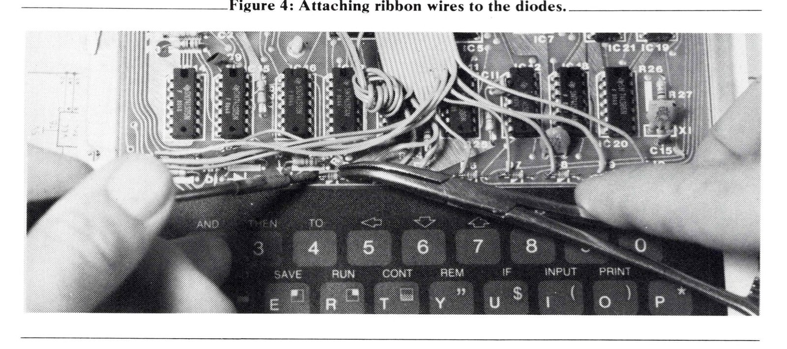
The final step of the basic conversion, connection to the computer board matrix diodes and resistors, was carried out using the DIP terminated jumper cable. One of the DIP plugs was cut off the cable, leaving enough cable on the detached connector so that conductor numbers could be positively identified. This was important because the jumper cable was not color-coded, although the 1/6 edge of the ribbon bore a standard red stripe. The computer’s top cover was removed. Following the convention of the IC socket on the KB, wires 1-8 were carefully soldered to the anode (unbanded) leads of diodes D3-D10 (MicroAce, D1-D8). Wires 9-13 were connected to the non-5 volt ends of resistors R13-R17 (MicroAce R18-R22; neither system is in numerical order!). To avoid component damage, wire leads were pretinned, and contacts were only briefly heated (Figure 4)
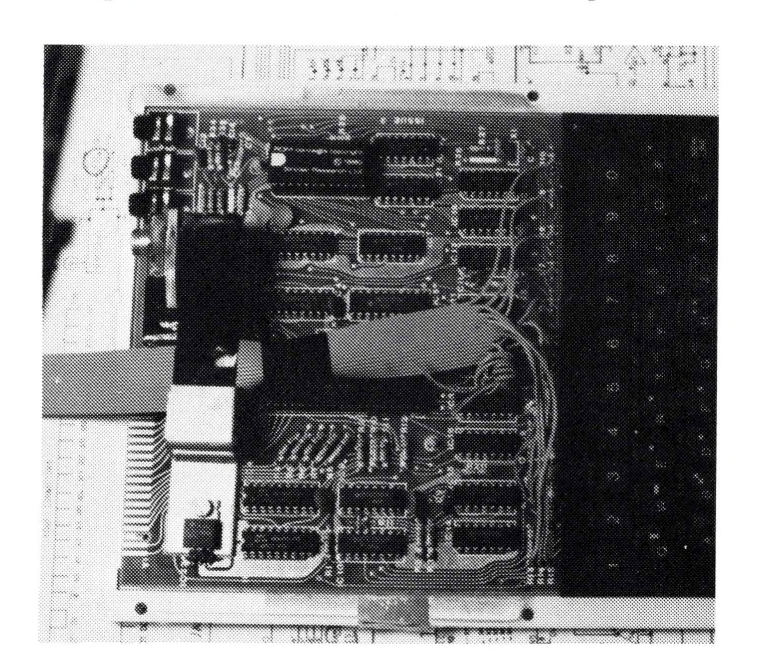
In my ZX80, the ribbon cable was led back under the voltage regulator heat sink to exit the case just above the expansion bus. (Other exits could be used in the ZX80 or MicroAce. For example, a small slot might be cut in the cover). Strain relief was provided by tethering the ribbon cable to the video modulator case. (Figure 5)
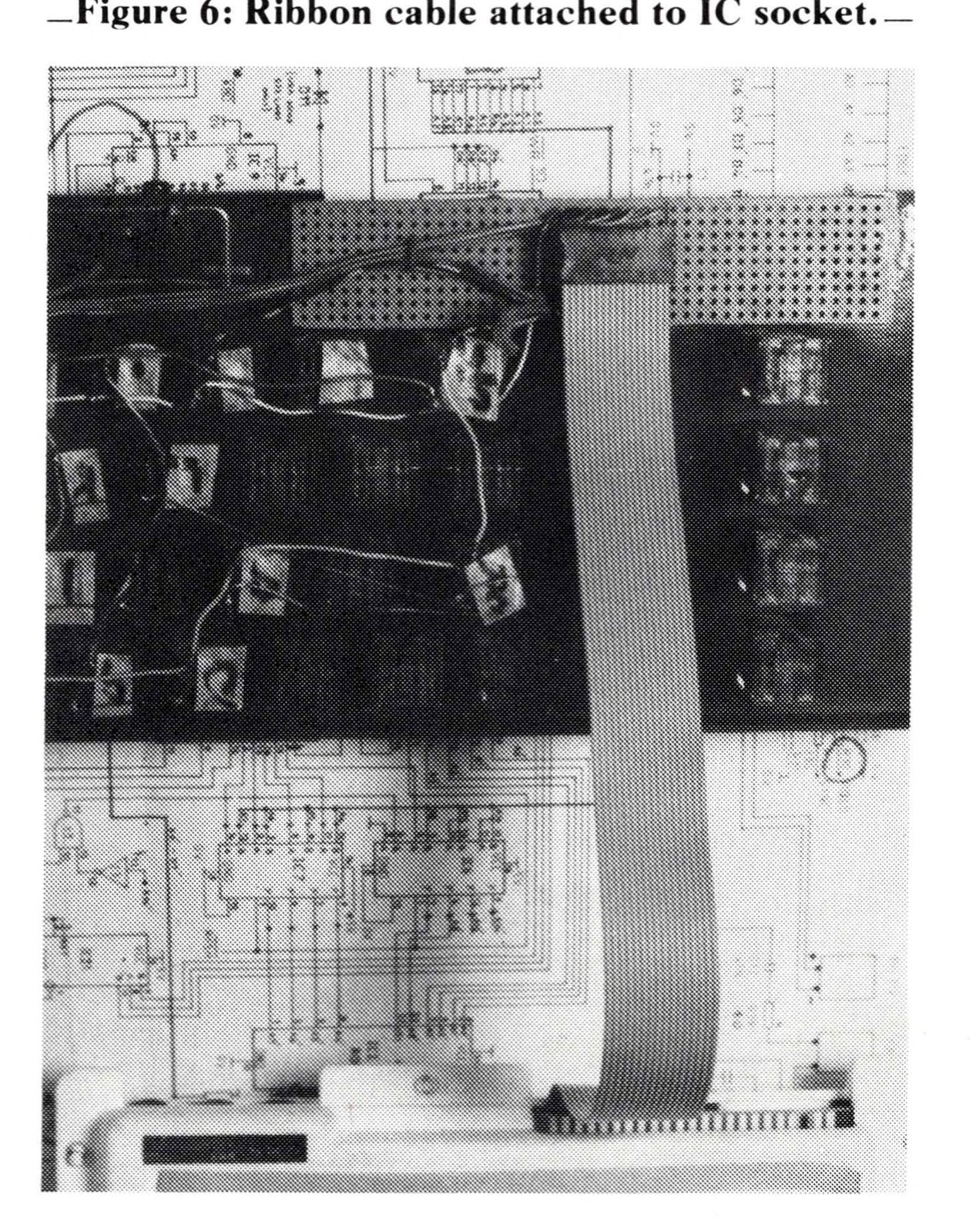
The final products of this conversion were a DIP-socketed, wired keyboard and a ZX80 with a mating ribbon cable “tail.” When the system was connected, everything worked—almost. Initially, the R and O keys did not function on the new keyboard. Closer examination showed that in wiring the matrix, I had slightly bent one terminal on each key so the switch contacts did not close. A gentle push on the terminal connection restored complete function. I then had a ZX80 with both keyboards functioning in parallel. (Figure 6)
In order to ruggedize the project and reduce TV interference from the conversion, a keyboard enclosure was added. I chose an aluminum housing for my system (BUD KB 13202 from Herbach and Rademan, Inc.; depending on the specific KB adapted, many other enclosures could be used). The IC socket on the keyboard was jumpered to another socket mounted on the back of the enclosure. (For courageous engineers who do not wish to test keyboard wiring before enclosing, connections from the rows and columns may be made directly to an IC socket on the cabinet). The connector pins on the computer’s new “tail” were protected during “stand-alone” operation using the remaining 16 pin IC socket.
Since the keyboard was printed with the standard type letters as well as with unusual “uppercase” functions, a copy of the ZX80 template was used as a “cheat-sheet.” Transfer lettering and clear epoxy lacquer also could have been used to identify keys.
Synopsis and Provision for Expansion
As described here, the basic keyboard conversion is easy to wire, taking a slow builder about four hours of straight time. The finished product as modified is a detachable keyboard for the ZX80/1 or MicroAce which can serve as the foundation for a more complex, expansion bus oriented microcomputer system. In the present form, the original system can be separated from the new keyboard, thus retaining true portability.
By implementing CMOS switching circuitry such as that obtainable from Schultz Systems, one can obtain advanced keyboard functions like auto-repeat and single-key rubout. By adding a separate cabinet containing a heavy duty power supply, printed circuit card guides, and ZX80 bus connectors, the true “hardware freak” can inexpensively construct a modular microcomputer system with features similar to those of more expensive business and scientific models. (A somewhat different approach to such an advanced system was shown in SYNC 4:38 “A Parallel Interface” by Alger Salt.) Design and implementation of these advanced features will be considered in a future article.
(Note: DEC, VT-103, and LSI-11 are trademarks of the Digital Equipment Corporation.)
ZX81 Conversion Details
Shortly after finishing the first part of this conversion article, I had the good fortune to acquire a ZX81 kit. It immediately became apparent that the same general conversion scheme could be applied to the new machine as well. I will detail only one approach, although SYNC readers will undoubtedly conceive of other ways to do the job.
The keyboard matrix and connector should be constructed as detailed above, with rows and columns wired to 13 pins on the attached DIP socket. The jumper cable should then be connected to the matrix diodes and resistors, which are D1-D8 and RP-3 in the ZX81. In the quick and dirty approach, the cable leads should be conservatively stripped, pretinned, and then soldered to the PC traces of connectors KB 1 and KB 2 on the solder side of the board.
Soldering may be done relatively easily with only the bottom half of the computer case removed. Figure 7 depicts the PCB under KB 1 and KB 2 and shows the order of connections for the lines of the jumper cable.
Stripping of the jumper leads should be kept to a minimum, and some additional insulation, like heat shrink tubing or silicone cement, may be used to reduce the likelihood of shorting. The cable may be out of the case below the bus connector, and tethering to PCB screw channel/support posts will help reduce the chances of wire breaks and shorts.
ZX81 owners particular about the “OEM” condition of their machines might want to try adapting a 16 pin dip plug to flexible printed circuit “cable” for direct connection to KB 1 and KB 2. This scheme necessitates opening the case, however, and disconnecting the membrane KB when connecting to the new KB. This is clearly no disadvantage for those who might wish to mount the ZX81 or bare PCB permanently inside the new KB enclosure.
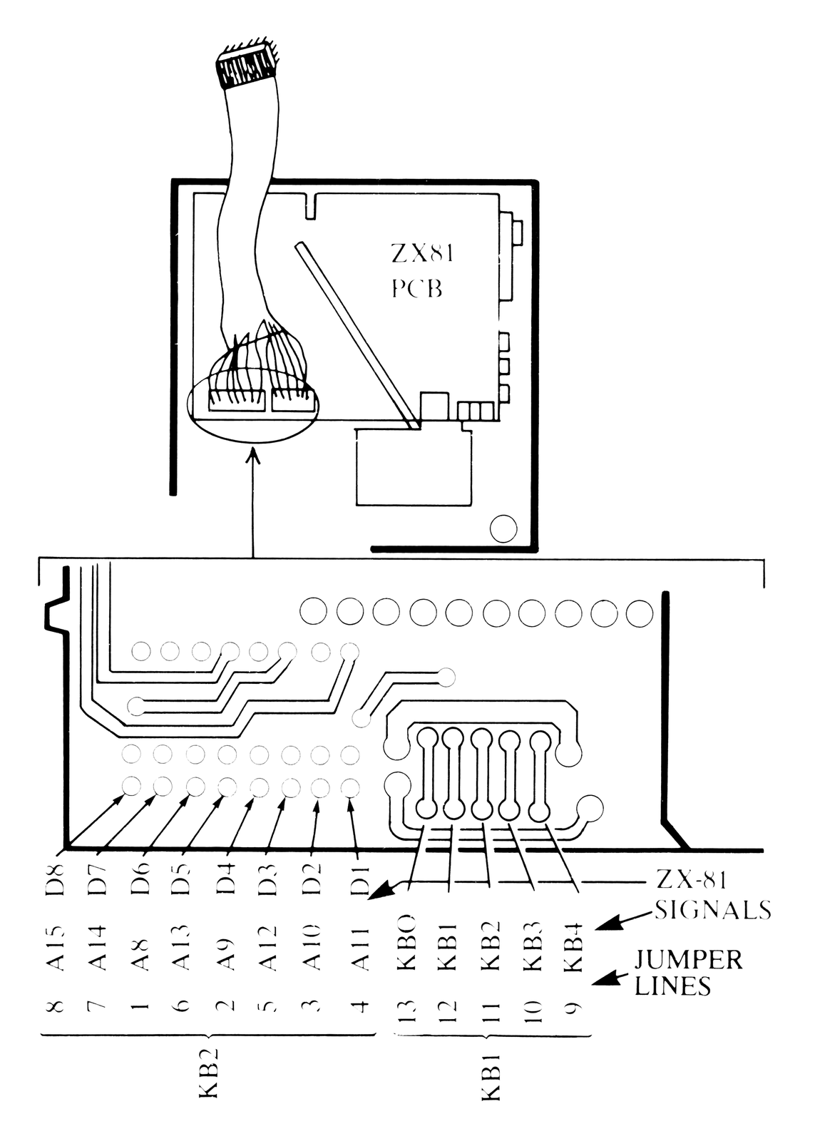
ZX-81 SIGNALS   D8   D7   D6  D5   D4  D3   D2   D1   | KB0 KB1 KB2 KB3 KB4
                A15  A14  A8  A13  A9  A12  A10  A11  |
JUMPER LINES    8    7    1   6    2   5    3    4    | 13  12  11  10  9
                ------------- KB2 -----------------      ------ KB1 ------