The Hunter board normally configured for the 8-16 K region of memory is required for SILICON MOUNTAINS‘ WRX16 SRAM HI-RES and is convenient to store many other utilities. The Larken EPROM is mapped at 12-16 K, creating a problem. How to use these devices together and most importantly, put ZX-TERM*80 on disk?
An arrangement to alternately disable the controller and NVM is one answer and is easily done. The principle is to switch off the Hunter board while reading from or writing to disk, then switching off the controller when disk operations are complete. Appropriate prompts and pauses are added to autorun programs to allow the switching. For instance:
1000 PRINT "REMOVE DISK...SWITCH FOR SRAM"
1010 PAUSE 4E4
1020 RUN
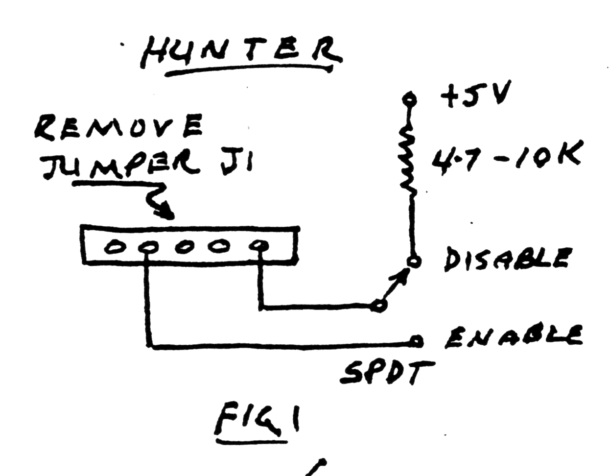
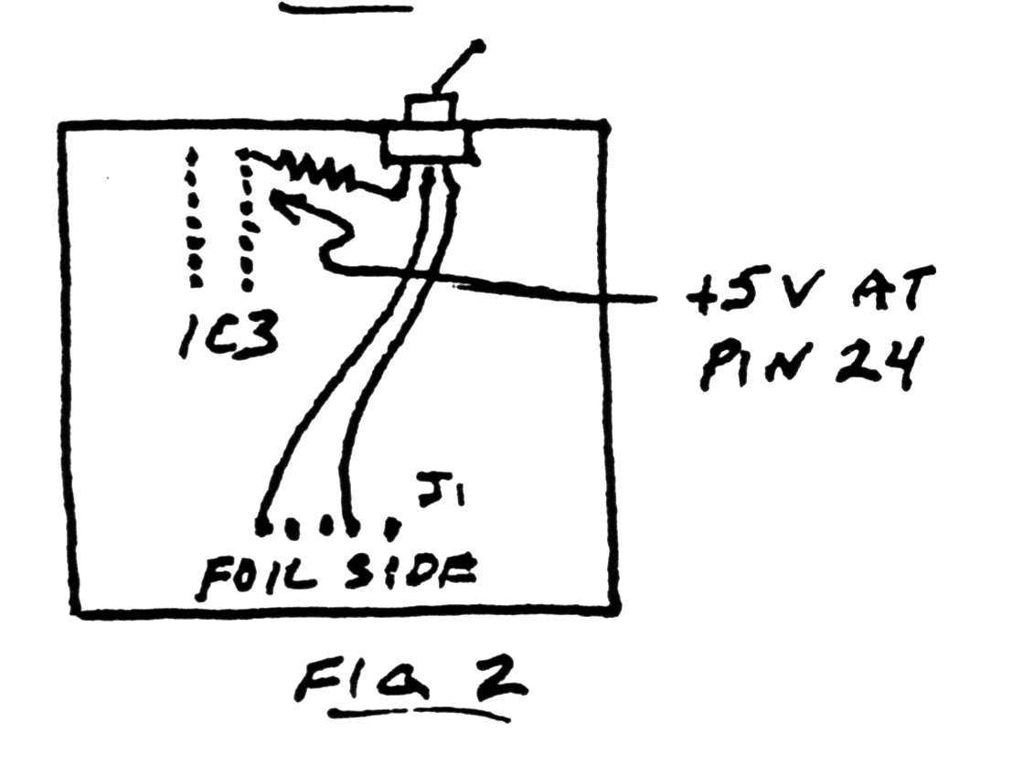
The Hunter board documentation shows how to install a disable switch. See figs. 1 & 2. The little switch can be superglued to the foil side of the board near the top.
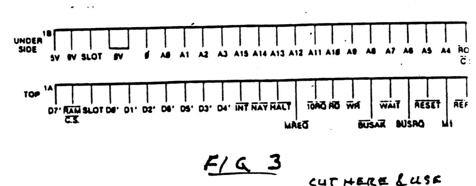
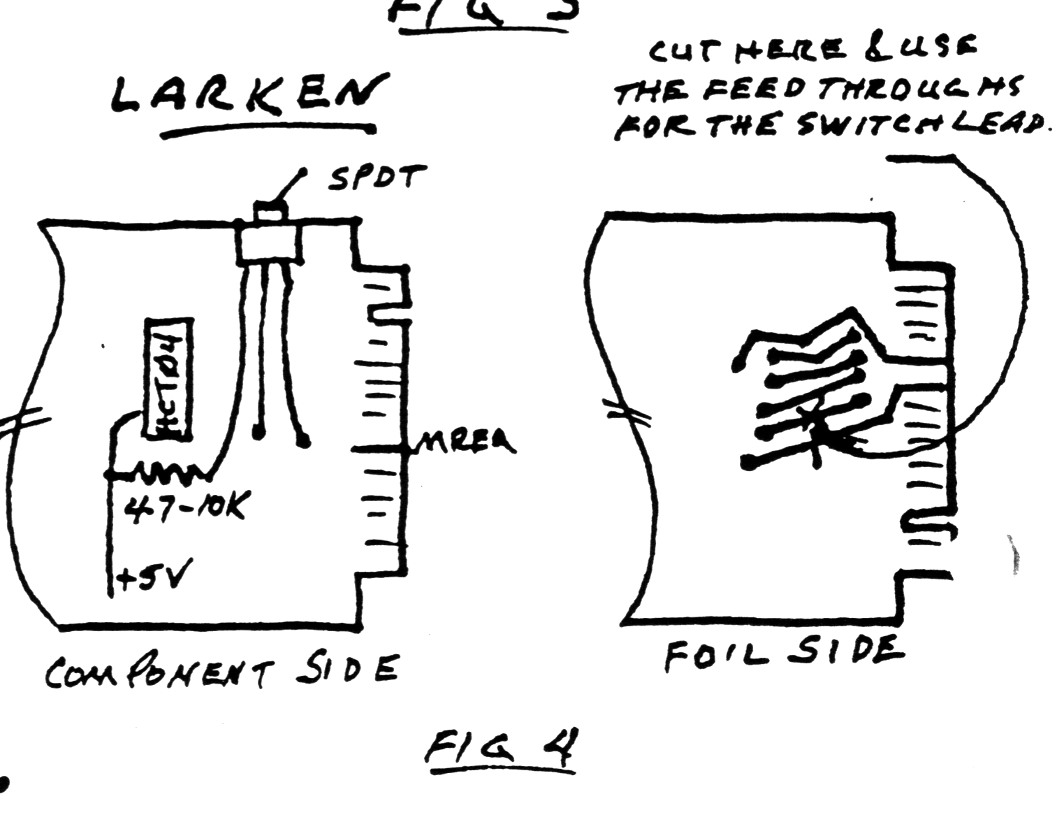
The method used to isolate the LARKEN board is similar. The MREQ line is cut and bridged with a switch.
Follow the trace from the edge connector, cut it at a convenient place and bridge the gap with a switch. Although MREQ is on the top (component) side of the edge connector, it is traced through and under the board. There are a number of unused traces and feed throughs here and I found it easiest to make the cut on the foil side and use the feedthroughs to the top to solder the switch leads. It is recommended that a pull-up resistor be used on the board side of the cut. There is a nice fat trace, Vcc to pin 14 of the HCT04 chip nearby providing 5V for a pull-up(4.7 to 10K). See figs. 3 & 4.
The switch can be fixed to the board with superglue or use some double sided foam tape to fasten the switch temporarily. Next time I will show how the board can be mounted in a readily found case.