

Many T/S 2068 owners have a desire to protect not only their 2068, but other valuables as well. But with the cost of “good” alarm systems costing hundreds or even thousands of dollars, most people would rather take the chance that they never will be ripped off rather than buy an alarm. It was hard enough convincing the spouse to let you spring for a 2068…and you know that you would never be able to convince your spouse to let you get an expensive alarm.
Well now you can kill two birds with one stone (as they say). You can justify your 2068 purchase as being practical, and you can also have a great alarm system…the alarm with high tech features and a LOW price! All that and it is easy to set up too! Here’s how:
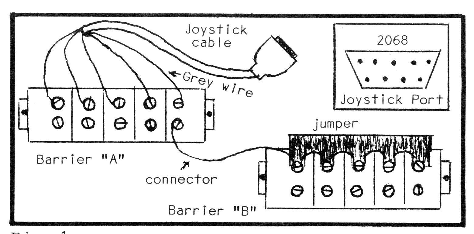
The heart of the alarm is the interface with the computer. All it is, is a jack plugged into either joystick port…or both if you want. Follow these steps to make it (Fig. 1). Also, please refer to the parts list for reference of the different parts that will be discussed.
1) Cut one end off the joystick cable.
2) Srip all wires except the brown, white, and black wires (these aren’t used).
3) Connect each wire to a screw on one side of a barrier strip.
4) Connect all screws on one side of the unused barrier strip with the jumper, then attach a wire between the unused screw in front of the GREY wire to any screw of the second barrier- on the same side that the eight-position jumper is attached. This wire is a common wire used for final connections.
The interface is now finished! I told you it was easy. Now comes the harder part.
You have a choice here. If you want the alarm to be able to tell you where a break-in has occured, you will have to run double wires to every detector in the house. The simple hook-up is to just make on big closed loop alarm circuit (see Fig. 2). Then you have one wire coming off the barrier strip, connecting between every detector, and a wire coming back to the computer completing the circuit. You probably would want to do it this way, as you might not care to know exactly where a break-in is occuring…you’ll be ready with your UZI.
To wire up the closed loop circuit, follow these easy steps. For detectors, I would choose items for normally CLOSED circuit alarms…if a wire is cut, it will sound the alarm. With normally open circuit alarms, a thief can cut a wire to disable the alarm. (Note: closed circuit magnetic switches are also cheaper than open circuit ones.)
With this 2068 alarm, if power to the 2068 is cut, NO alarm will sound. However, it is highly unlikely for a burglar to cut power to a house…why should he bother? If he knows there is an alarm, he would usually stay away for fear of setting off the alarm…and he would know that most alarms these days have battery backup anyways, so cutting power wouldn’t help. Now on to the loop.
1) Determine where you want to mount detectors (magnetic switches, window foil, vibration detectors, window sensors, ect.). Hook them up to the door or window as directed on the package. This usually involves screwing in two screws and/or pressing tape in place. Not hard stuff.
2) Using 20 or 22 gauge stranded wire (or whatever you you prefer, single conductor, ect.), run a wire from a screw on the common barrier (connected to the GREY wire), to one terminal of whichever detector is closest to the computer (see Fig. 2, part A).
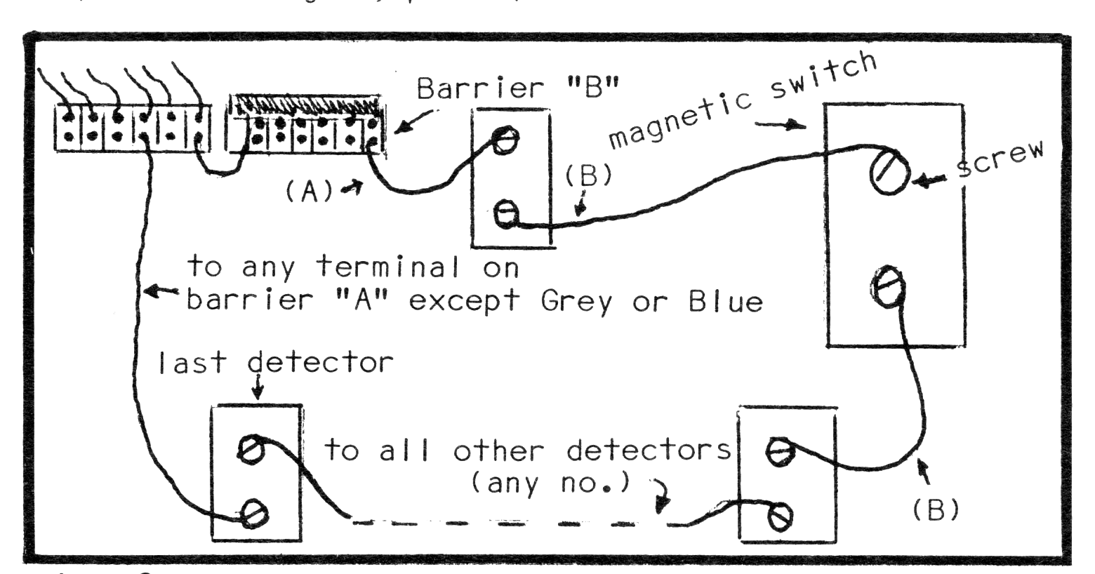
3) Now run a wire from the second terminal of the detector to a terminal on the next nearest detector. Continue stringing detectors together as in Fig. 2, part B.
4) Now that all the detectors are connected, run a wire from the open terminal on the last detector to the screw on the barrier in front of the GREEN wire.
Now to test out the loop, plug the joystick jack on the left or right side of the computer, whichever is easier and enter the following program lines:
10 PRINT STICK (1,1)    ...this line is for the left jack.
20 GOTO 10
If the right jack is used, replace line 10 with…
10 PRINT STICK (1,2)RUN the program. If ones are printed on the screen, the loop is working! Congratulations! If zeros are printed, the loop has a break in it somewhere…go back and check. If you find no break, you may have to try the program six times, each time connecting the returning wire to a different screw on the barrier of wires. All joystick cables that I bought had the same color coding; it is possible that Radio Shack could have pulled a “switch” on you.
Now all you have to do is enter the following program as your alarm’s “brain”. This is a very simple program…no bull has been added. If you want to add color, print statements, ect., go ahead!
10 REM ***ALARM SENSOR PROGRAM
20 INPUT "Hit (ENTER) to activate alarm"; a$
30 PRINT "You have 30 seconds to leave."
40 PAUSE 1800
50 IF STICK (1,1)=1 THEN GOTO 50
60 PAUSE 1800: REM 30 sec. entrance time
70 FOR X=1 TO 5
80 FOR Y=1 TO 300
90 BEEP .1,20: BEEP .1,30
100 NEXT Y: NEXT X
110 GOTO 50: REM resets alarm after 5 min.
If you are using the right hand joystick port, substitute line 50 with the following line…
50 IF STICK (1,2)=1 THEN GOTO 50That’s all there is to it! You can have an output to an amplifier from the MIC jack of the computer…or to a stereo system. When the alarm sounds…WOW! With the right volume it should be enough to scare the hair off a gorilla! You can create an extremely powerful and annoying sound with the BEEP loop and an external amp. Experiment for your own favorite sound.
Now for the hardest part of all. IF YOU HAVE SETTLED ON THE SIMPLE CLOSED CIRCUIT ALARM ABOVE, YOU DON’T HAVE TO READ FURTHER. I will now explain how to make the sophisticated system which will allow you to tell exactly where a trouble spot is. You will have to run a wire from the computer to every detector.
1) Follow step one above for detector hook-up.
2) Now you will have to run a wire from each terminal on barrier A, to one terminal on each detector (see Fig. 3). USE OPEN CIRCUIT DETECTORS ONLY-FOR SIMPLIFICATION OF THIS VERSION OF THE CIRCUIT.
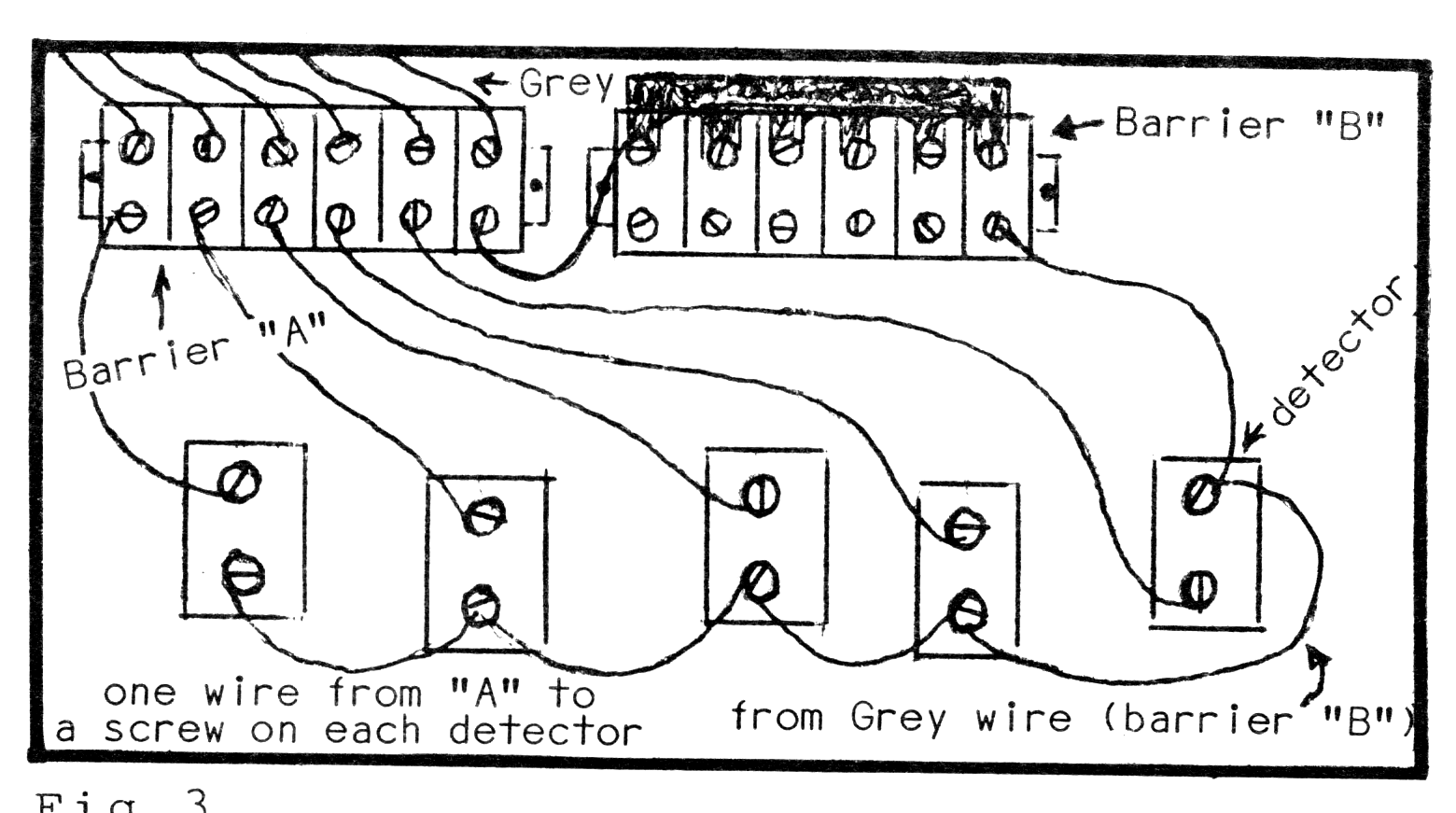
3) You can now either run a wire from each terminal of barrier B (GREY wire) to the unused screw of each detector, OR run a wire from each screw of the barrier B to the unused terminal of the closest detector. Then connect to this wire another wire running to the unused screw on the next closest detector. Keep stringing the unused screws of each detector together in this manner until you are finished (see Fig. 4).
4) Now to test all the loops, plug the jack into either side of the computer, then enter and RUN the following test program:
10 PRINT STICK (1,1)         ...for left side joystick port
20 GOTO 10
Use this alternate line 10 for right joystick port.
10 PRINT STICK (1,2)Only zeros should be printed on the screen. If any numbers are printed, check the connections, AND MAKE SURE THE WINDOWS AND DOORS THAT THE DETECTORS ARE ATTACHED TO ARE CLOSED!
Now check to see which color wire is connected to which detector. If the red wire runs to a detector in the living room, write this down, ect. You will have to assign variables in the program according to where each wire runs. In the program, assign the variables in line 20, according to this: a$=red wire, b$=green, c$=yellow, d$=orange, e$= blue wire. The blue wire is the wire which normally goes to the joystick button, and the computer uses STICK (2,1) to detect if the button is pushed…button is device #2 (see 2068 users manual, page 174). Now the program:
10 REM *** Sophisticated Sensor Program
20 LET a$="den": LET b$="kitchen"
Note: see instructions above for line 20. Enter the variables according to what you wrote down (above).
30 INPUT "Press (ENTER) to activate alarm";z$
35 PAUSE 1800: REM 30 sec. exit delay
40 IF STICK (1,1)<>0 THEN GOTO 100
Note: use STICK (1,2) for joystick port on right side.
50 IF STICK (2,1)=0 THEN GOTO 40Note: use STICK (2,2) for joystick port on right side.
100 PAUSE 1800: REM 30 sec. entry delay
110 LET break=STICK (1,1): IF STICK (2,1)=1 THEN GOTO 500
Note: for right joystick port use STICK (1,2) and STICK (2,2) respectively.
120 IF break=8 THEN LET w$=a$
130 IF break=2 THEN LET w$=c$
140 IF break=1 THEN LET w$=b$
150 IF break=4 THEN LET w$=d$
160 PRINT "BREAK IN AT ";w$
170 FOR x=1 TO 5: FOR y=1 TO 300
180 BEEP .1,20: BEEP .1,30
530 NEXT y: NEXT x
540 GOTO 40: REM alarm reset after 5 min.
SAVE the programs. LOAD them whenever you want to run the alarm. You can change the PAUSE values to vary the enter/exit delay. To turn the alarm off after you enter, either hit break or turn the machine off.
It is assumed that you would usually have the screen off or in a room where you will be able to see it while the alarm is active. The best place to have the computer is within about twenty seconds of the entrance, so if you know that the alarm is active, you have time to turn it off. An un-suspecting burglar would be unsure of his surroundings and would linger long enough to set off the alarm. If you have the computer hooked up to an amplifier, he will NOT stick around to see what kind of alarm it is!
If you need to hook up more than 5 detectors, make another interface for the other jack on the computer. Wire it up just like the first one, but add this line to the programs…if simple circuit is used:
50 IF STICK (1,1)<>1 THEN GOTO 60
55 IF STICK (1,2)<>1 THEN GOTO 60
57 GOTO 50
Note: use<>1 if closed circuit detectors are used,<>0 if open circuit ones are used, in lines 50 and 55.
This will allow another set of 5 detectors to be hooked up…if more are needed, contact me (address at end of article), as it is possible.
If the second alarm program and circuit is used, add this line to the program:
25 LET f$="bedroom 1": LET g$="bedroom 2"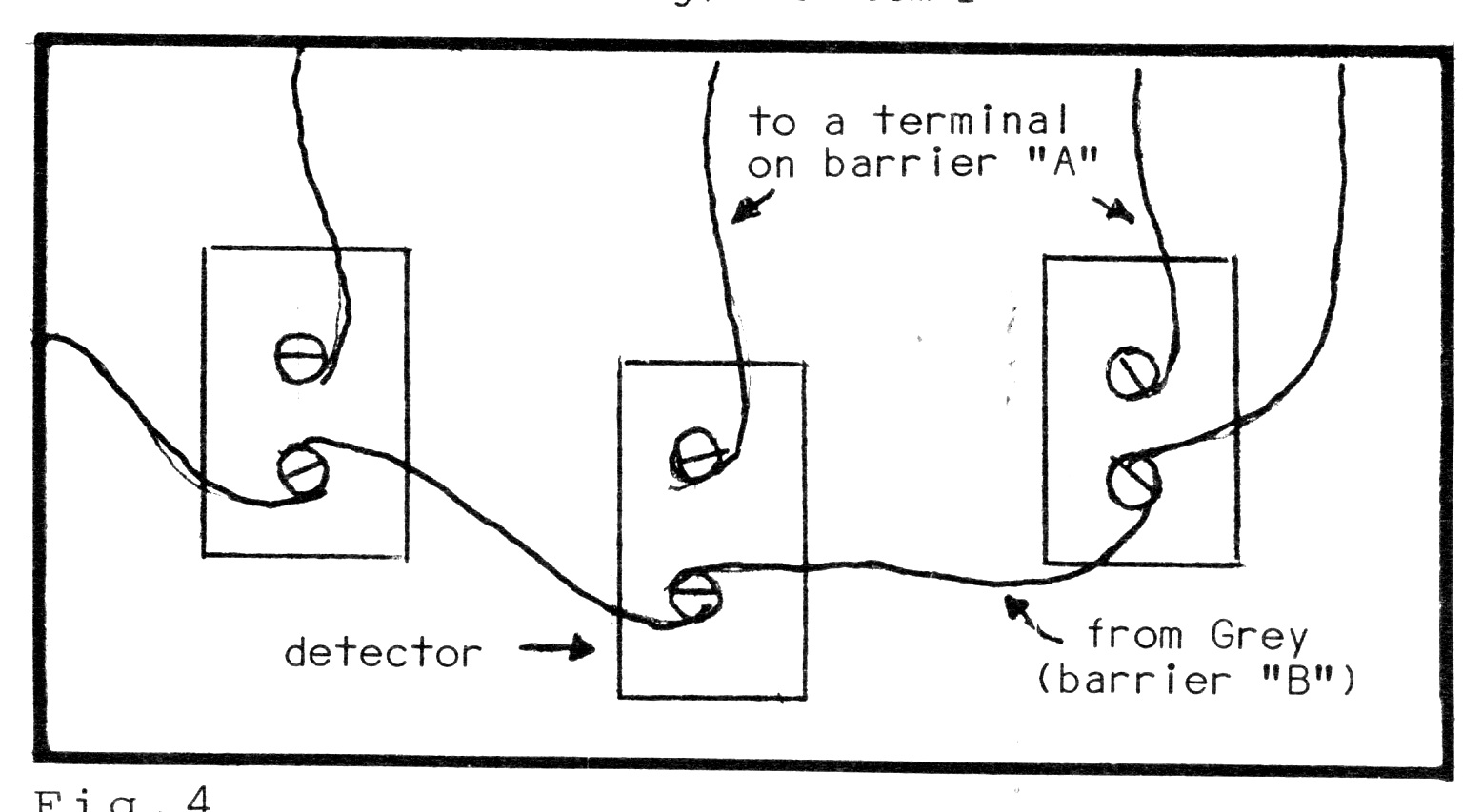
Note: define another six variables the same way you did for line 20, going around writing down which wire goes to which detector.
40 IF STICK (1,1)<>0 THEN GOTO 100
45 IF STICK (1,2)<>0 THEN GOTO 100
50 IF STICK (2,1)<>0 THEN GOTO 100
55 IF STICK (2,2)=0 THEN GOTO 40
110 LET break=STICK (1,1): LET break2=STICK (1,2): IF STICK (2,1)=1 THEN GOTO 500
115 IF STICK (2,2)=1 THEN GOTO 500
151 IF break2=8 THEN LET w$=f$
152 IF break2=2 THEN LET w$=h$
153 IF BREAK2=1 THEN LET w$=g$
154 IF break2=4 THEN LET w$=i$Note: blue wire on new jack=j$ remember.
500 IF STICK (2,1)=1 THEN LET w$=e$: GOTO 505
502 LET w$=j$
505 PRINT "Break in at ";w$
SAVE the program, and run to test. Make sure all doors and window detectors are attached to, are closed. You can pretend a break-in is occuring by tripping a detector. See if the program is accurate. If a detector in the living room is tripped, the program should say “Break in at living room”. If it says something else, you may have made a mistake in assigning the variables.
FURTHER TIPS: It is easy to hook up the wires around the house…use a staple gun. Then you can paint over wire and staples to camouflage them. You can use a continuity tester (Radio Shack, $1.95) to test closed circuit loops for breaks. If the loop is complete, the tester beeps. This device can come in handy for isolating trouble spots. No, I don’t own Radio Shack… it just seems that everyone lives near and RS store, so to make things as easy as possible, I have recommended use of all Radio Shack parts. This minimizes the trouble in finding the right part…you don’t have to search all over the country for some strange “wigizmbo”.
PARTS LIST
Joystick extension cord RS #276-1978
2 Dual row barrier strips #274-659
eight position jumper #274-650
magnetic door/window    switches- closed
circuit, #49-495, open circuit #49-512
see article for more info
glass breakage detector # 49-516
window foil items, #49-502,504,518
wire-22 guage stranded #278-1296 (90 feet)
It may be possible to add a BYTE-BACK BB1 Control Module to your 2068, and then when the alarm is tripped, the module can be used to control an external alarm bell, lights, auto-dialers, ect. To minimize cost and trouble, I have not included this device or any like it in my plans for the alarm. You can add whatever you want though. I am interested in hearing how others may utilize this program and idea of using the joystick jack for uses besides joysticks. Please feel free to drop me a line with your comments, questions, ect. to: Joe Newman, [address omitted].