
TECH TALK
If you where one of the lucky people who purchased a Rotronics Wafadrive but was unable to obtain the parallel printer cable or your cable has been damaged, here is a way you can make your own cable.
Three parts are needed:
A 36-Position Flat Cable Connector (Centronics Type) Radio Shack #276-1533
A 26-Contact Card Edge Connector (IDC Style) 3M #925130-26-R
OR
A 34-Contact Card Edge Connector (IDC Style) Radio Shack #276-1564
3 to 5 foot of flat (ribbon) cable. 25 or 36 conductor. Radio Shack #278-772 #278-774
I recommend the 3M connector which is used to connect to the back of the Wafadrive because it is the exact size needed. But, since this may be a difficult part to obtain, you may also use the Radio Shack 34 contact connector, but you will have to use a hacksaw to trim off one side in order for it to fit on the edge card of the Wafadrive.
The wiring diagram for the two connectors is below. Since this is a centronics interface at the Printer’s end, the cabling should be the same for any printer, but check your printer manual first. This cable uses all of the Wafadrive’s parallel lines but does not us all of the printer’s parallel lines.
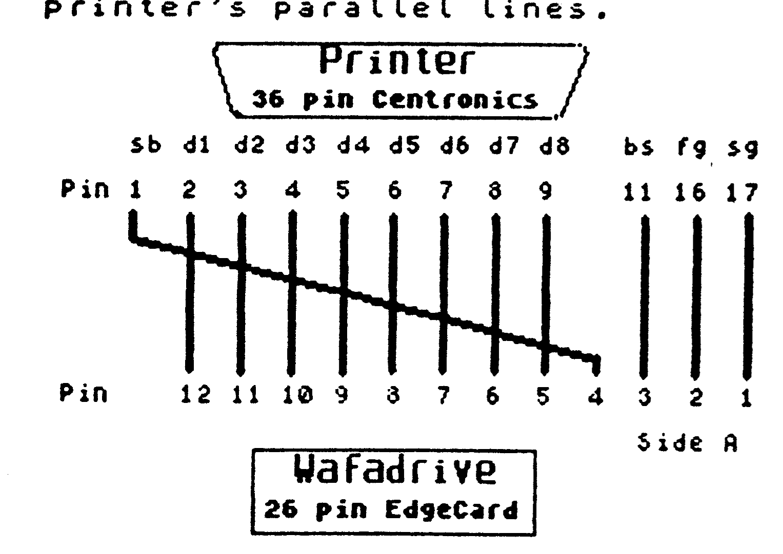
(NOTICE: ISTUG and/or the author is not resposible for any damages to equipment resulting from information contained in this article.)
The lines are defined as follows:
Printer   Line            Wafadrive
  pin     name               pin

  1       Strobe              4
  2       Data Bit 1          5
  3       Data Bit 2          6
  4       Data Bit 3          7
  5       Data Bit 4          8
  6       Data Bit 5          9
  7       Data Bit 6         10
  8       Data Bit 7         11
  9       Data Bit 8         12
 11       Busy                3
 16       Frame Gnd           2
 17       Signal Gnd          1
Start by attaching the 26 (34) contact card edge connector to the ribbon cable (Remember to remove any extra/unused wires from the ribbon cable first so that only 26 or 24 are used.)
Crimp the connector so that the small metal V’s line up one per conductor. These V’s are used to break the casing and make contact with the bare wire. Crimping tools are recommended, but I find that a small shop vice works extreamly well.
Now take the other end of the ribbon cable, and using a sharp hobby knife, carefully remove/cut away the Eighth line from the left side of the cable (see Hint below) so it is no longer attached to the conductor to the right or left of it. Make sure not to cut through the insulation such that the copper wire is exposed. Pull back and remove this line for about an inch and a half. Do the same to line one, except cut this line off after it is pulled back (it is not used.)
HINT: To find the eighth line, hold the edge card connector with slot facing you, and count along the ribbon cable from right to left. NOTE: If you are using a 24 conductor ribbon cable, you need to find the sixth line to cut away and pull back. This line is the STROBE line and must connect to Pin 1 of the Centronics connector.
The next part requires you to take the Centronics connector and position it on the ribbon cable so that the wide end is toward the edge card connector.
Position the eighth line in the V of the Centronics pin 1. Now place the remainder of the ribbon cable on the V’s (pins 2 through 9, and 11) remember that pin 10 is left unused. It is also important to note that most printers will not use pins 16 and 17 so I recommend that they are not crimped/used.
Very carefully, crimp the Centronics connector keeping the eighth (sixth) line in pin 1. Lastly, use a continuity tester to check all connections so that they match the schematic on the left before attaching and using it on the Wafadrive and printer.