
This article is especially geared towards those brave (or foolhardy) souls who enjoy fooling with the innards of their computer. Although the circuit described can be built on an external card perfectly well, it is somewhat unique in that it can be installed inside your TS2068, without interfering with the normal operation in any way! What I will be describing is a ‘Kempston’ type joystick port. This type of joystick has become THE most used joystick with the ZX Spectrum, and a good 90% or better of the Spectrum software is configured for this type of joystick.
This internal port will be wired in parallel with the right hand Timex joystick port. Although the same connector will be used, the two ports have independent operation. This means that any jostick plugged into J6 (the right socket) will be able to be read by means of the STICK command in 2068 BASIC, by the command IN 31 in 2068 or Spectrum BASIC, or by machine code I/O commands accessing port 1Fh (the Kempston port).
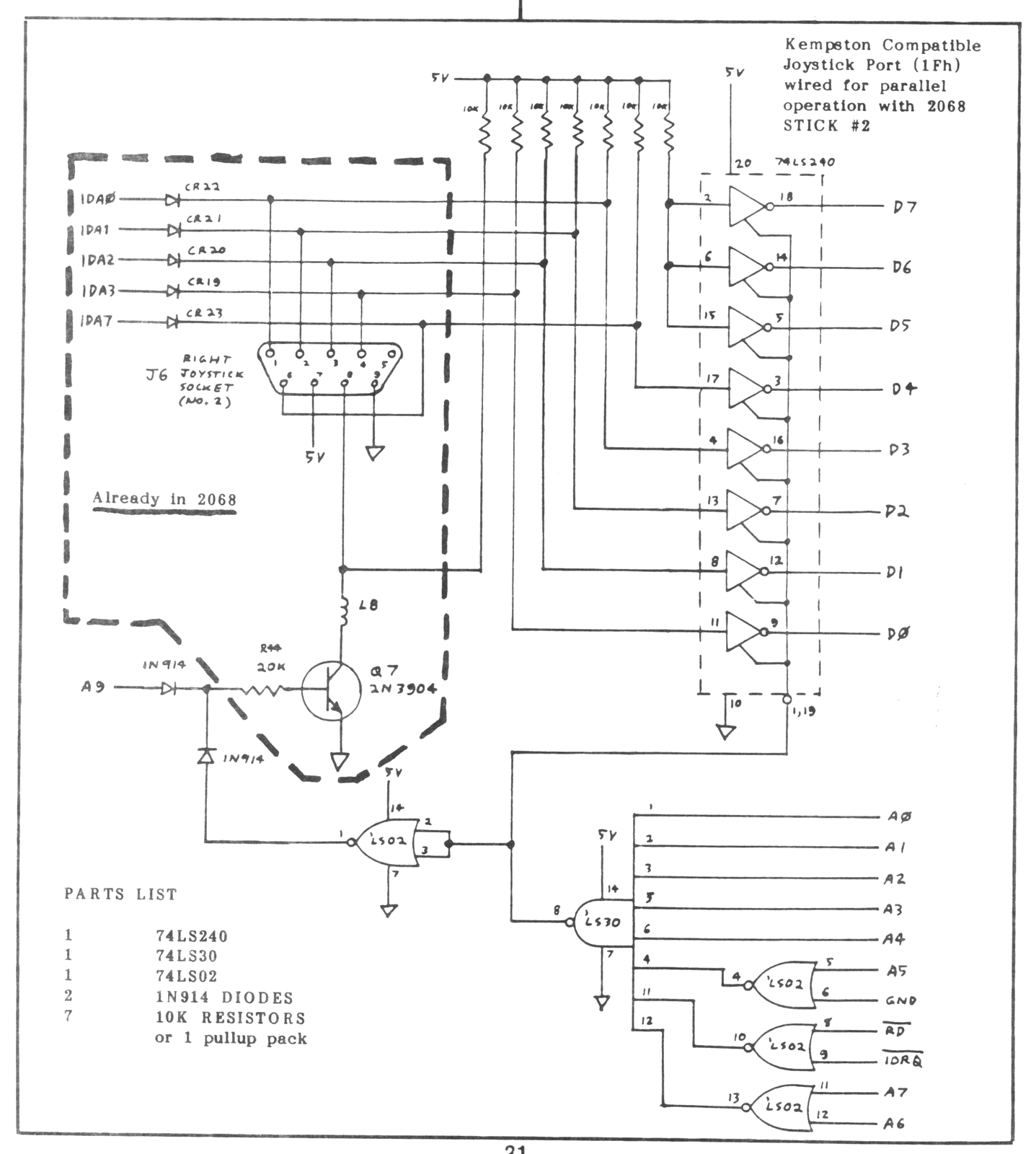
The circuit requires only three IC’s, one pullup resistor pack, and two computer-type diodes. Looking at the schematic, we can see that the 74LS02 and 74LS30 form the I/O address decoder, and the 74LS240 buffers and inverts the joystick data. The inversion is necessary because the Kempston standard calls for high-active output, and I needed low-active data at the joystick itself in order to make the parallel hookup. The last gate of the 74LS02 is used as an inverter to provide the base of Q7 with a “turn on” signal whenever the new port is accessed. To allow both signals (the Timex joystick port and the Kempston port) to access Q7 without damaging it, resistor R44 is disconnected at the A9 address connection, and one of the two diodes is added in series with it. Then, the second diode is connected from the R44/diode junction to the output of the 74LS02 “inverter.” In order to provide the buffer with reliable data, all of the buffer inputs have pullup resistors.
For actual construction, I suggest a small piece of perfboard (about 2″ by 1″) as a mounting board. The 2068 has a conveniently empty area right by the right joystick port, which can be used for the board. PLEASE NOTE! I have absolutely no way of looking over your shoulders, and in NO WAY can I be responsible for any modifications which you choose to make to your computer! Therefore, BE CAREFUL!
I am not going to give exact details of the construction, partly because it is relatively simple, and partly because there may be a couple of different 2068 printed circuit boards. Refer to the schematic whenever necessary, and use an ohmmeter to check for the proper signals.
To test your new toy, carefully reassemble your computer and turn it on. Test for proper operation of the Timex and Kempston joysticks with a looping line like that below:
10 PRINT AT 10, 10; STICK (1,2); AT 12, 10; STICK (2,2): AT 14, 10; (IN 31): PAUSE 5: PRINT AT 10, 10; " "; AT 12, 10; " "; AT 14, 10; " ": GOTO 10If the numbers you see on the screen match those below, you have a working Kempston/Timex joystick.
         UPPER     MIDDLE     LOWER
UP         1          0          8
RIGHT      8          0          1
DOWN       4          0          4
LEFT       4          0          2
FIRE       0          1         16
Remember that the numbers are additive as far as diagonal directions.
Well, that’s the whole set of directions. I hope that many of you are able to use this circuit, and I invite any comments.