
In this installment, we’ll start taking a closer look at the BLACKJACK listing of Vol. 3, No. 4, to get an idea of what makes it all work. But before we get down to brass tacks, a few other comments are in order.
TS2068 USERS
Are you impressed with the 2068’s capabilities, but just a little confused about how to go about using it to the fullest? Well, don’t feel too bad; it’s actually a pretty complex machine. Even the way its display file is mapped can be pretty confusing. SRAM HI*RES, on the other hand, is simplicity itself. Its display file is arranged very simply as 176 (or 192) lines of 32 bytes each, going from left to right and top to bottom.
So why not dig up that old “doorstopper” and experiment with SRAM HI*RES for a while! Its ease of use and abundance of nifty commands will give you lots to experiment with, and (more importantly) learn from. Once you’ve mastered SRAM HI*RES, you’ll be in a much better position to tackle the intricacies of the 2068.
So here’s an “invite” to you 2068ers to join in the fun. Come on in, the water’s fine!
WRX16 HI-RES AND INTERNAL 64K
At this point, let’s give credit where credit is due. As you may know, SRAM HI*RES Extended BASIC is a collection of new commands that make use of a high-res core routine developed by Mr. Wilf Rigter. This routine is an invention anywhere as significant as the original “cheap video” system employed in the ZX81. Without this core routine, all the neat possibilities that SRAM HI*RES has to offer would be completely useless. With no other hardware requirement than a static RAM in the 8-16K region, this routine is what gives your humble ZX/TS a whole new look, not to mention new worlds of possibility.
The hardware aspect brings me to another point. You may have noticed that the BLACKJACK listing in the last installment was directly followed by Tim Stoddard‘s 64K BUILT-IN RAM. I checked over the schematic, and guess what? Tim’s circuit will work fine with WRX16 and SRAM HI*RES with NO CHANGES! This is because the chips’ OE* (output enable) is pulled low if EITHER the RD* line goes low, OR the REFSH* line goes low. Note that Tim reports compatibility with “THRUST“; guess what THRUST is based on? You guessed it… WRX16.
So, dig up a TS1000 somewhere (I’ve seen them sell for as little as $15), add about that much more in RAM chips, invest a couple hours of easy hardware hacking, and add SRAM HI*RES. You now have a full 64K computer with high-res capability, at a total cost of under $60. What a deal!
A QUESTION OF SYNTAX
What is meant by “syntax?” No, it’s not a payment to your government for vices like tobacco and beer. The dictionary defines it as “The arrangement and interrelationship of words in phrases and sentences.” The computer definition could be worded very similarly; “The arrangement and interrelationship of commands and parameters in program statements.” For example, there is a definite way of plotting a pixel to the screen in Sinclair BASIC. You have to say, “PLOT x,y”. You can’t say “x PLOT y” or “PLOT x AND y”. If you don’t use the correct syntax, the computer won’t know what you’re talking about; much as if you told someone, “Dog man bites.” (Does dog bite man, man bite dog, or does dogman generally bite?)
People who write extended language packages (as extended BASIC) for ROM-based computers have a bit of a problem. How do you add new commands to an immutable chunk of silicon? Obviously, we can’t (easily) change or expand the ROM itself. Fortunately, there are always other ways of doing things. You are probably used to passing your parameters (like x and y in the PLOT example) using POKE, and executing the command with RAND USR…. Sure, it works. It works quite well. The problems are that this can be confusing (unless you use dedicated variables), and more importantly it’s very extravagant with memory. To take an extreme example, let’s say you have to pass four parameters (as for a DRAW command). You might have to say something like,
1000 POKE 20001,X1
1010 POKE 20002,X2
1020 POKE 20003,Y1
1030 POKE 20004,Y2
1040 RAND USR 22000
If you’ll do a byte-count of these lines, you’ll find that to draw a single line on the screen from (X1,Y1) to (X2,Y2) takes a total of 98 bytes!! It doesn’t take long to fill up 16K at that rate!
In comparison, let’s look at how SRAM HI*RES would handle the same command:
1000 IF USR HR THEN LPRINT DRAW;X1,X2,Y1,Y2Verify that this statement takes only 27 bytes. We can therefore do over 3-1/2 times as much drawing in a given memory space! If we condense the word DRAW to D, then we save three more bytes, without affecting the operation of the command.
Another point has to do with expressions. In Sinclair BASIC, we can say exotic things like, “PLOT 2*ASN (X/2),Y+3/(LN (C/D))”. Some extended BASIC systems require you to first assign the value of the expression to a single-letter variable, or POKE the expression into some machine-code variable first. Not SRAM HI*RES! To change the above command to SRAM HI*RES syntax requires only that we precede it with “IF USR HR THEN…” That’s all it takes!
Consider the statement “IF USR HR THEN…” as nothing more than a prefix that tells your computer that it is supposed to do something in high-res. Don’t worry about “what if not USR HR?” etc. This syntax construct is nothing more than a bridge, or a door, into SRAM HI*RES. There are other subtleties regarding high-res syntax, such as the significance of semicolons and commas in PRINT statements, which we’ll get to in the course of this series. For now, simply get comfortable with all those IF USR HR THEN… prefixes; remember that ALL they mean is that we’re doing something that we can’t do in normal BASIC.
Similarly, the prefix IF USR HR THEN LPRINT… is simply our way of adding new commands with the greatest possible flexibility in using expressions. We call these the “Group 2” commands, as opposed to the “Group 1” commands like IF USR HR THEN CLS, IF USR HR THEN PLOT x,y and so on. Obviously, there are no Sinclair BASIC analogs to commands like SPRITE MOVE, DRAW, DEFINE UDG, etc.
THE AMAZING UDG
What is it that REALLY sets high-res BLACKJACK apart from previous Blackjack games for the ZX81/TS1000? Is it the game itself? No. In fact, the core for this game was originally written on the first 2K TRS-80 pocket computer! It performed flawlessly, if with a few less features. No, the appeal of high-res BLACKJACK is in the pictures of the actual cards themselves, right there on your TV screen. It is the GRAPHICS that turns a good but rather ho-hum game into something that will make your friends ooh and aah over your “monster doorstopper”.
The key to these pictures is a thing called a “UDG”, for “User-Defined Graphics.” Though it sounds rather ominous and forbidding, it’s really very simple. A UDG is nothing more than a screen character that YOU define. Unlike the 128 fixed characters in your ROM, the 128 UDGs can be defined and changed at will. Every character, UDG or ROM-based, consists of eight rows of eight dots, for a total of 64 dots. Each of these dots are either set (“ink”) or reset (“paper”). The possibilities are staggering. I once computed that if you printed all the possible UDG’s on TS2040 paper, 32 UDG’s per line, the length of 2040 paper you’d need would equal the circumference of the orbit of Pluto.
The EASIEST way for a user to define UDGs is by using direct binary, as does the 2068. In other words, “0” represents a reset pixel, “1” represents a set pixel. The only problem with this is that it is tremendously memory-inefficient. For each UDG definition, we would need 64 bytes, plus the “syntax overhead” (punctuation between groups, etc.) Well, so let’s use decimal numbers to give the value for each of the eight rows. After all, everyone has ten fingers, right? Unfortunately, 10 is not an integral power of 2; this makes decimal FAR more confusing, in the long run, than other bases like octal or hexadecimal.
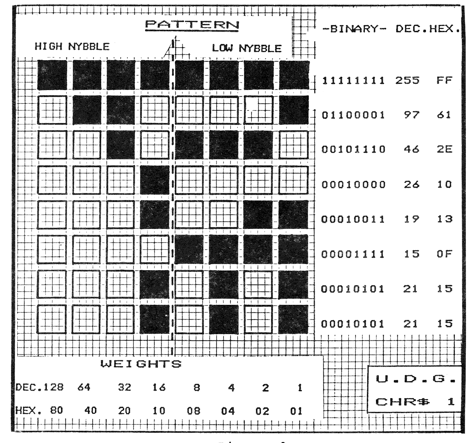
The most memory-efficient approach, while maintaining ease of decoding is (you guessed it) hexadecimal. Time for a philosophical digression. I cringe every time I see an article by some neophyte, arguing something to the effect of, “if God had wanted us to use hexadecimal, He would have given us sixteen fingers,” or “if my computer understood hex, I could enter hex numbers as program lines.” I cringe not so much because the author is missing the whole point, rather out of embarrassment because I once felt the same way. However, the deeper you delve into the workings of your computer, the more you are forced to realize that it really IS a “base 2” device (i.e. nothing but ON or OFF). It is very frequently REALLY handy and NECESSARY to be able to quickly convert between a number and its binary equivalent, or vice versa. It is much, much easier to do such conversions using hexadecimal. If you really need the decimal equivalent, look it up in a table or have your computer figure it out using one of the many conversion routines that have been published. A case in point is defining UDG’s.
Take a look at Fig. 1. The UDG character depicted there is an actual UDG used in the BLACKJACK program. If you compare it to the screen dumps published in the last installment, you’ll see that this is the upper-left corner of the image of the KING card (the left side of the crown at the top of the card). Each row of pixels is “disassembled” in binary, then in decimal, then in hexadecimal. Note that, in the top row, all pixels are set (darkened). Note that each bit (pixel) in this row represents a power of two. The rightmost bit is 2^0=1, the next to the left is 2^1=2, the next is 2^2=4, and so on. So, to figure out the value in decimal, we have to add 1+2+4+8+16+32+64+128 and finally come up with 255. There MUST be an easier way.
Rest assured. There is an easier way. Simply split your image down the middle, as shown by the dotted line in the diagram. So now, each row of eight bits (= 1 byte) is broken into two rows of four bits (= 1 nybble). Now consider the following table of binary-hex equivalents:
0000=0 0001=1 0010=2 0011=3
0100=4 0101=5 0110=6 0111=7
1000=8 1001=9 1010=A 1011=B
1100=C 1101=D 1110=E 1111=F
Commit this table to memory. Burn it into your mental EPROM. Practise it until you’re SURE that 1011 means “B”. An easy way to cheat (comparable to counting on your fingers) is to remember that the “weights” (going from left to right) is 8, 4, 2, 1. So “1011” is 8, plus (no fours), plus 2 (9, A) , plus 1 (B). Another way to cheat is to keep the above table handy.
OK, now here’s the punch line. To convert a binary number to hex, simply break it into nybbles as described above, then convert each nybble to its equivalent single-digit hex number. The resulting two-digit hex number gives the hex equivalent! For instance, the third line in the diagram is binary 00101110. Breaking this into nybbles we get 0010 (2) and 1110 (E) = 2E. It will take very little practise to get the hang of this; it won’t be long at all before you can figure out the hex equivalent of any 8-bit binary number by simple inspection. To figure this same number out in decimal, we would have had to add 32+8+4+2. Don’t know about you, but I’m tempted to reach for a calculator when I see something like that.
How does this apply, in practise, to SRAM HI*RES and the BLACKJACK program? Take a look at line 9001. What we’re telling the computer here is:
IF USR HR THEN ..... [enter SRAM HI*RES]
LPRINT U; ..... [Define UDG]
" ", ..... [starting at space = CHR$ 0]
"00,00,00... etc." ..... [hex numbers for each row]
Note that the first eight entries, corresponding to the Sinclair “space” character, are all zero. In other words, our UDG CHR$ 0 is a space just like the “normal” character set. This is where the similarity ends.
Note that, as listed, the “separator” after the eighth hex pair is the graphic symbol on “1”. This was simply for my convenience in entering and debugging; in fact, the separators can be anything your heart desires. SRAM HI*RES completely ignores them. The point to remember is, that you can make your UDG definitions as long as you like. The LPRINT UDG; (or LPRINT U;) command keeps processing hex numbers, assigning them in sequential order, as long as they are supplied. So, line 9001 defines the UDGs corresponding to all the characters from CHR$ 0 (space) through CHR$ 9 (graphic on D). Line 9002 starts defining at CHR$ 10 (graphic on S) and continues to CHR$ 19 (“<“). And so on, until all 128 possible UDG characters have been defined.
Before we end off, what do we mean by UDG’s “corresponding to” the standard Sinclair characters? Very simple. When using the UDG PRINT mode (selected by IF USR HR THEN PRINT;;;;) then anything containing these characters will print as the corresponding UDG instead. For instance, if we said IF USR HR THEN PRINT;;;;CHR$ 1, then the computer would print the UDG shown in the diagram of Figure 1.
REMEMBER: In SRAM HI*RES, you can generally use the same syntax constructs as you are used to in Sinclair BASIC. So, any of the following statements would be perfectly valid, and would do the same thing:
LET A$=CHR$ 1
IF USR HR THEN PRINT;;;;A$

IF USR HR THEN PRINT;;;;"▒"

IF USR HR THEN PRINT;;;;CHR$ (2*SIN(PI/6))
NEXT TIME…
More on UDG’s … SPRITES … F-SAVE MAGIC … MORE SRAM-HI*RES PHILOSOPHY