
I have read many articles on correcting the over heating problem due to the 5.0V regulator (7805), which supplies the regulated 5.0V to the QL. When you look inside the QL, I wonder if SIR Clive’s miniaturization caused more problems, than it was worth.
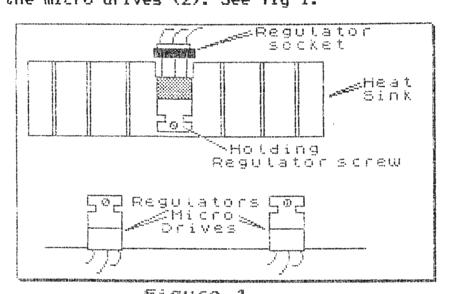
1) In correcting the problem with my QL, I decided to remove the source of the problem, the REGULATOR and its HEAT SINK. By removing the eight screws on the bottoms of the QL case and opening the QL, the only task to perform was to remove the one screw holding down the 5.0V regulator, and remove the regulator from its socket. With the regulator removed, the heat sink will now lift out. The only power components remaining which would add to any or very little heat is the regulator for the micro drives (2). See fig 1.
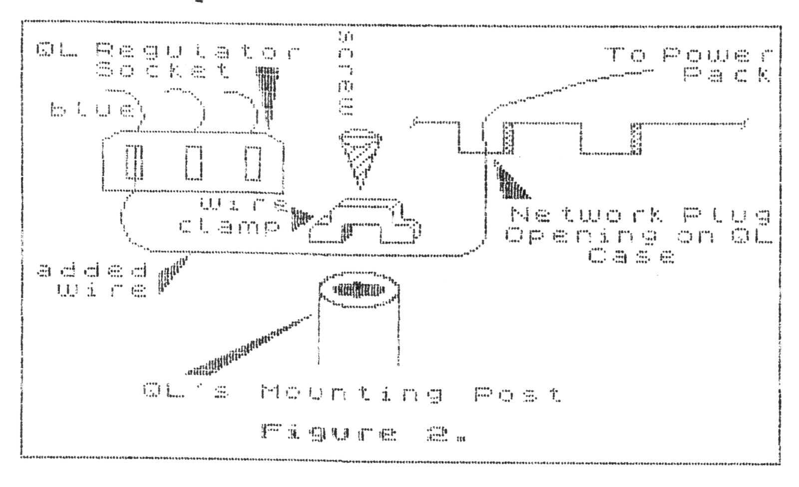
2) Obtain a wire about the length of the cable from the POWER PACK to the QL. Strip one end of the wire and insert the striped end into the input slot of the regulator socket, see fig. 2. I then cut a small piece of conductor lead from a old IC and soldered the striped end of the wire to it, and then inserted it into the regulator socket. Using a small wire clamp (plastic), the wire was then fastened using the screw which was used to hold the regulator in place. This will now hold the new added wire and prevent the wire from coming loose. The remaining wire was fed through the opening in the QL, the opening used for the Network plug. This wire will be used as part of the old power cable. See fig. 2. This completes the modification to the QL. The remaining steps are to add the 5.0V regulator to the QL externally, as part of the power cable as shown in fig. 3.
3) POWER CABLE: Measure about 6″ to 10″ on the power cable, from the Power Pack end. Cut the cable at this point. This is the point where the 5.0V regulator will be inserted and connected. The regulator will now be in series with the QL, and part of the power cable.
4) PARTS needed: 1 mini box the size to hold the regulator heat sink or larger. 2 Rubber grommets, inner hole size, for the power cable. 2 capacitors; a .1uf 35v and a 1000 uf 35v. NOTE: I used a different regulator, a UA323 with a higher current rating (3A). The original regulator (7805) with its QL heat sink will work fine.
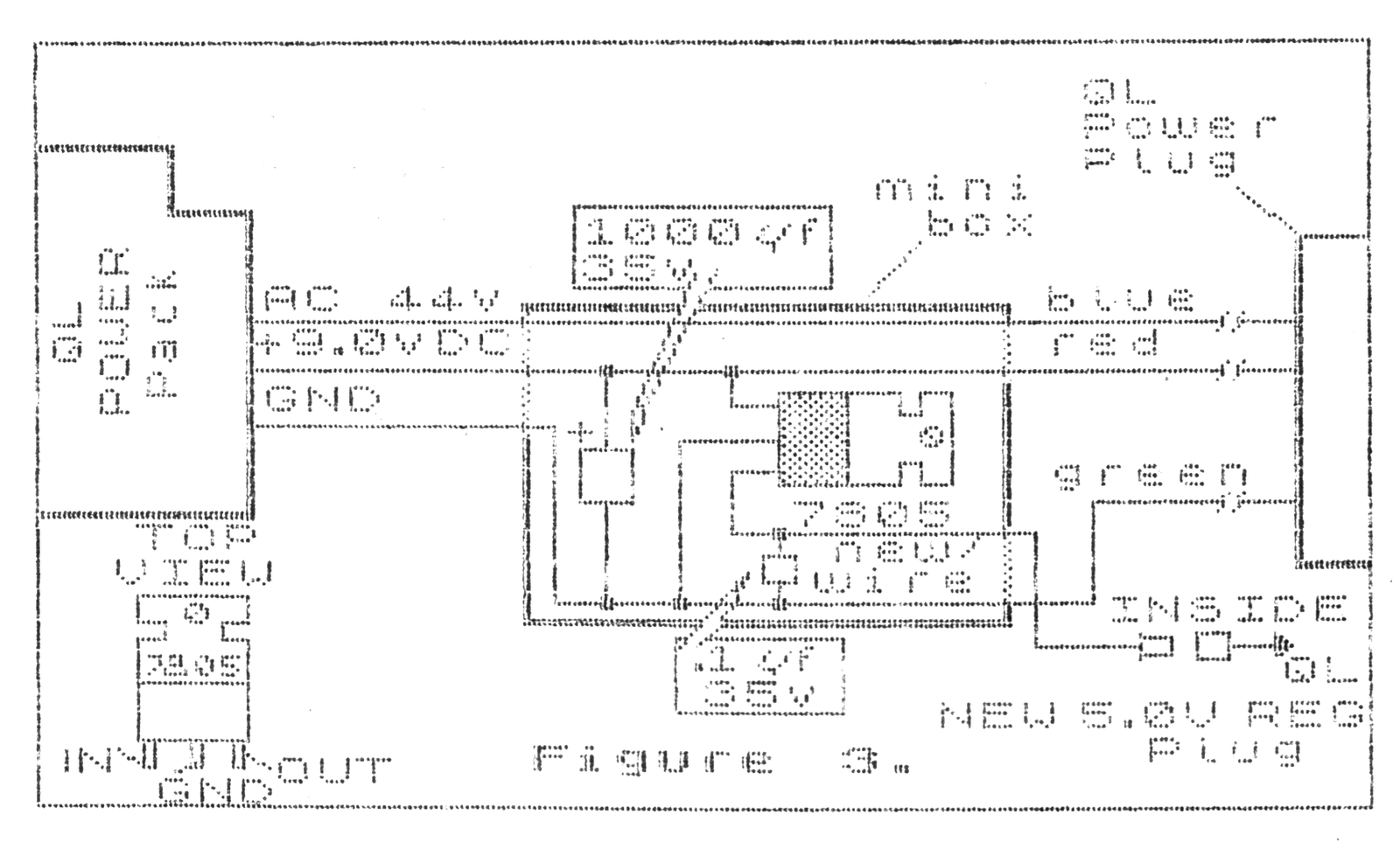
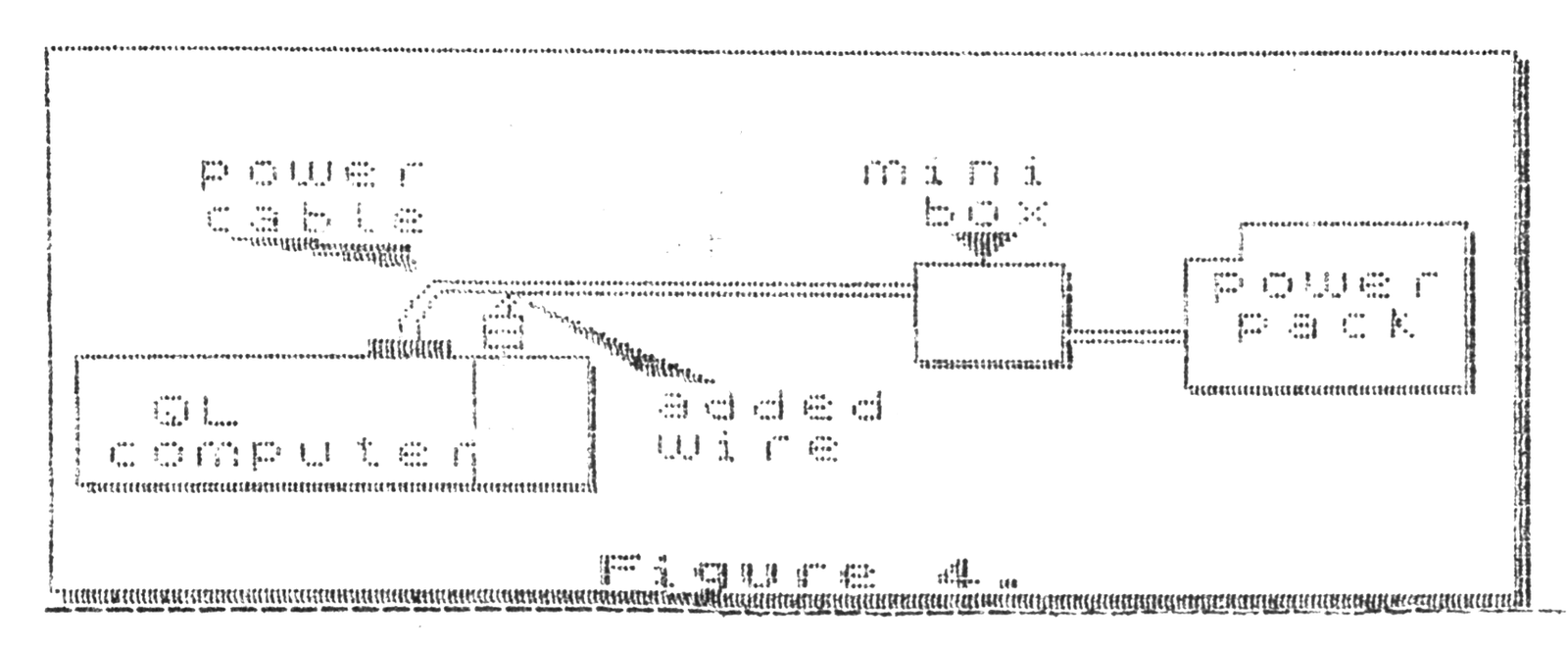
5) On each end of the mini box, drill a hole and insert the grommet. Mount the heat sink to the outside of the mini box (top). Insert each end of the cut power cable into each hole of the mini box and wire as per drawing. See fig. 3. It should only be done by a person, with a background in electronics. I did not go into detail on dimensions, you may want to mount the regulator and heat sink some other way. The extra wire was taped to the power cable and a small plug was used for a quick disconnect at the QL. The main idea was to show how to remove the regulator from the inside of the QL. The QL now runs COLD.