Larry Crawford / London Ont / Canada
11 Jun 93
Frank Davis
P.O. Box 1095
Peru IN USA
46970
Dear Frank
Sorry to be so long in getting this off to you but things have been rather hectic around here.
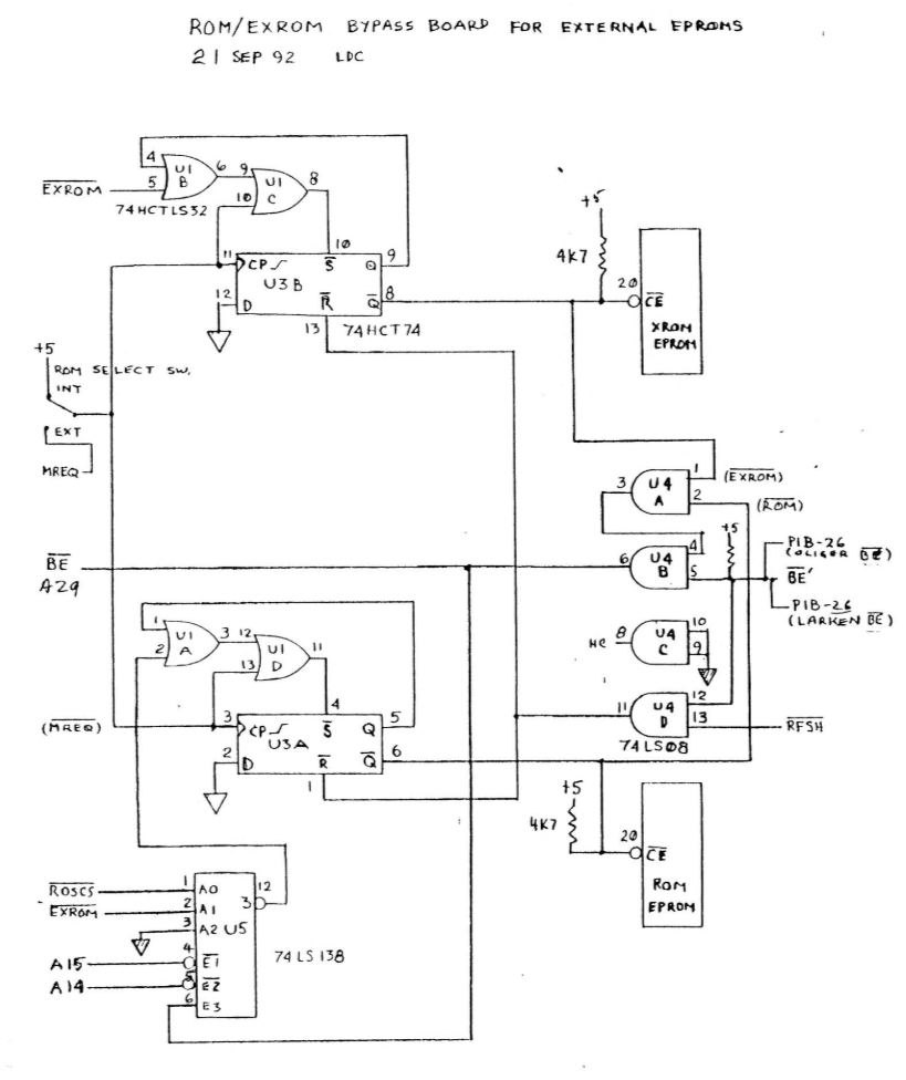
You have Bill Pedersen‘s schematics, etc. He, of course, could not physically try them out so I tried out his ideas on my own bypass board until we got it working.
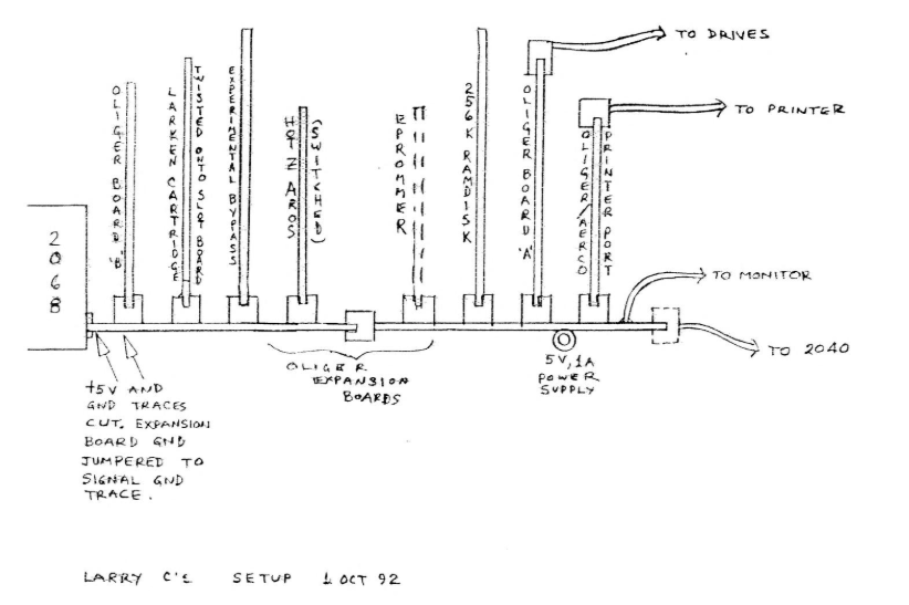
Enclosed are the schematics of my version. There doesn’t seem to be any similarity between the two versions but in fact the logic is the same. A couple of years ago I hand-wired a board on perfboard and used switches to select internal or external ROM and EXROM with wires running from inside the 2068 case to the board. It worked fine but was crude.
The schematic on page 1 uses Bill’s logic and works fine and completely externally. I have removed my internal switches and wires out to the board. Bill was to have PCBs made up of his circuit and I was going to stuff them for him but alas, he passed away too soon.
In any case, his logic works and the boards would work. He was in the process of rewriting the ROM and EXROM codes but couldn’t finish. I am completely ignorant of the internal workings so can do no more than I have.
Enclosed are copies of my latest version of Tasword which you may find of some interest.
Best wishes,
Larry C.


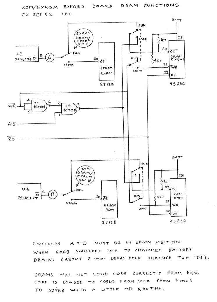
Switches A & B must be in EPROM position when 2068 switched off to minimize battery drain. (About 2 ma leaks back through the ’74).
DRAMs will not load code correctly from disk. Code is loaded to 40960 from disk then moved to 32768 with a little M/C routine.
Image Gallery