
Correct cassette loading problems
The signal booster consists of one miniature audio transformer. The transformer is used as an interface between the computer and the cassette player.
Examples:
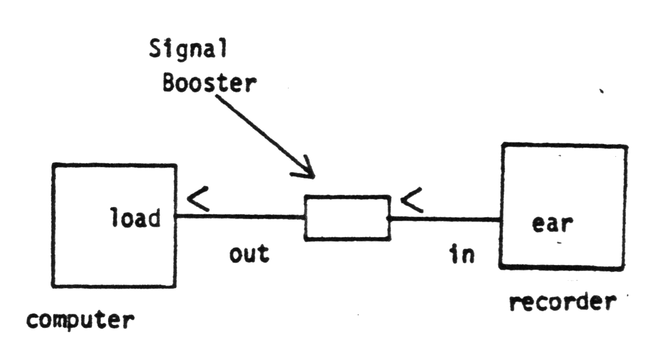
The signal booster has the following advantages:
1. Isolates the computer from the cassette player, which eliminates noise.
2. Increases the audio signal amplitude.
3. Cassette player volume setting can be adjusted to a lower level, thus improving the signal/noise ratio, this lower level setting decreases the inherent noise caused by high level of volume setting of volume control of most cassette players.
4. Increased signal amplitude, allows for misalignment of the record/playback head, which causes low signal amplitude.
5. No power required.
6. LOW COST.
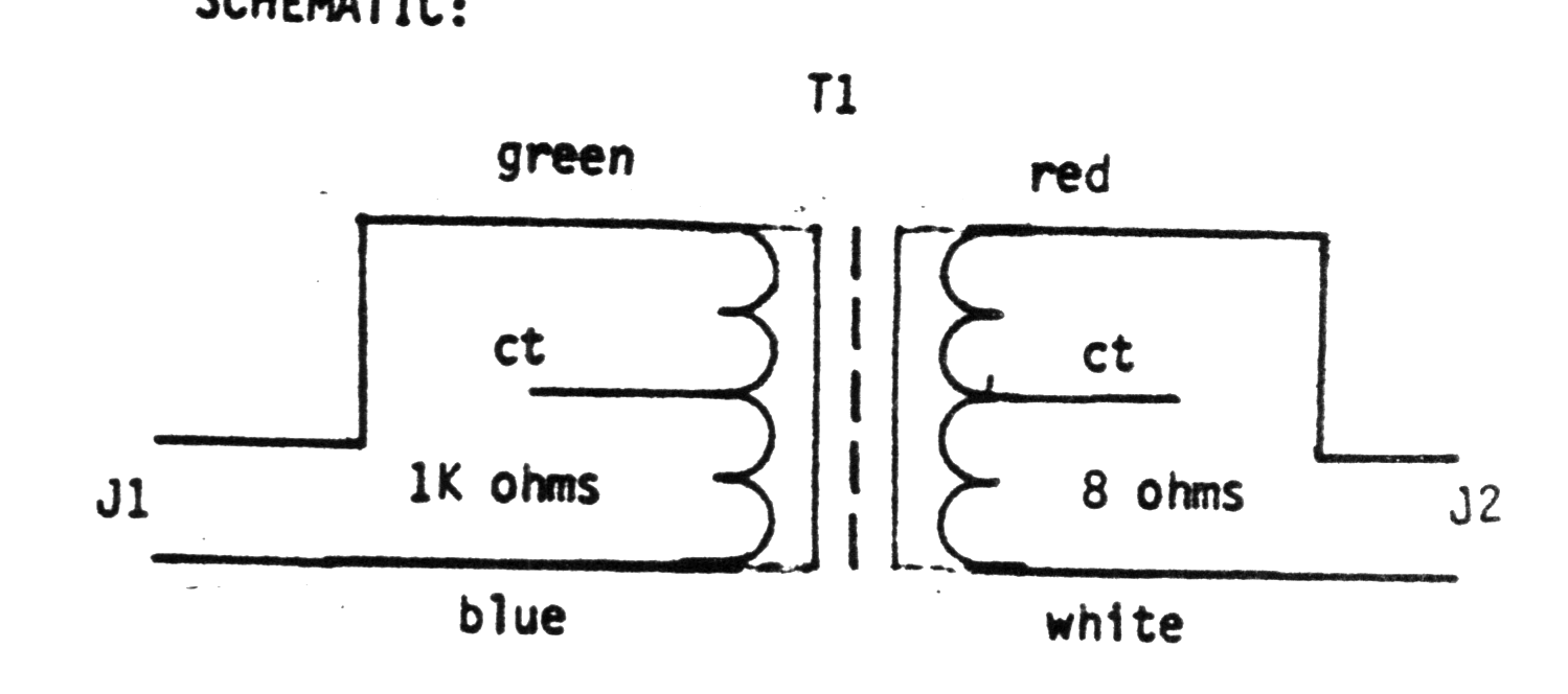
SCHEMATIC:
CONSTRUCTION
1. Drill two .250 (1/4 inch) holes in a plastic pill bottle, one through the cap, and the other through the bottle bottom.
2. Solder transformer leads to jacks (J1) and (J2) as per schematic, then insert into the plastic bottle.
NOTE: Don’t use a metal container, the metal prevents proper isolation and grounding btween the computer and the cassette player.
Parts List
1. T1 – 1K to 8 ohms (Radio Shack 273-1380)
2. J1 & J2 (Radio Shack 274-297)
3 Plastic pill bottle to fit transformer T1
When using signal booster, use a lower volume setting for best results.
Reprinted from the May/June issue of SINCUS NEWS
Retyped by G.F.C.