Lots of people have trouble loading programs. This loading level indicator may help. This circuit does not reduce the recorder’s output.
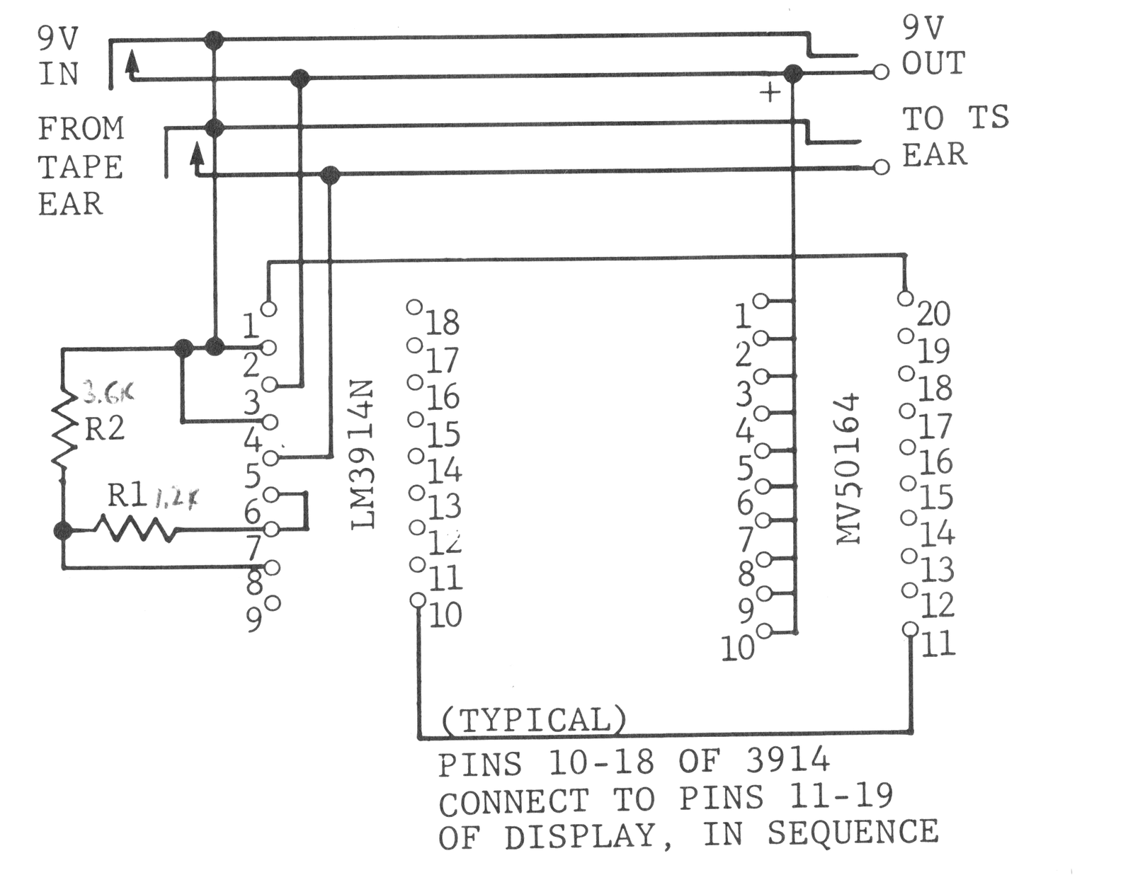
We chose to build an electronic level meter with LED bar-graph display using parts available at Radio Shack stores and many other distributors. This indicator plugs in-line between your computer and the power and ear cables. In use, the position and brightness of the LEDs show the output amplitude of your tape recorder.
All zero-volt (ground) connections for both power and signal should run individually to a tie point capable of accepting eight wires (one is a spare). Every lead must travel individually to this tie point–do not use shared wires to make any zero-volt connections. Attach leads from pins 2 & 4 of the LM3914N to this tie point. One end of R2 must connect here as well as the 4 zero-volt leads from jacks.
Brightness of the LED display depends on R1. Current in the LEDs equals 12.5/R1 units where R1 is in kOhms. We used the standard 10 mA drive and thus set R1=1.2kOhm. A quarter-watt resister will suffice.
Sensitivity depends on both R1 and R2. But with R1 chosen, R2 alone determines the extra signal needed to light the next LED. Use the formula V=1.25 (1+R2/R1) to calculate the voltage at which the 10th LED just lights. We want this to equal 5.0 volts, but we likewise want to employ standard resistor values. Our choices are: (1) use precision resistors of 1.2k & 3.6k; (2) use standard resistors of the same values and run uncalibrated; (3) use standard resistors of 1.2k & 3.9k and trim the 3.9k value for calibration. We used standard resistors and read relative levels.
If you want to calibrate your indicator, disconnect the ear cable. Apply a 5.0 volt signal (available at pin 1B of the ZX/TS bus) to the input lead (pin 5 of the LM3914N) and try resistors parallel to the 3.9k. Start with 27k and work upward, substituting standard resistors in sequence until the 10th LED goes out. Use the last resistor that lights the 10th LED. (This procedure also works for a 3.6k resistor in the upper half of the 5% tolerance permitted. It fails for resistors of 3.9k at the low-tolerance edge, but you can substitute another. It’s unlikely to be as low-valued.)
You can also do this trimming with a known good tape connected to the computer, and trim R2 until the 9th segment gives a bright, steady display during the program portion of the tape.
We used the following major parts from our local RS: LED display driver, LM3914N, RS276-1707; bar graph display, MV50164, RS276-081; and Experimenter’s dual IC board, RS276-159. When using a different board, get one that accepts 20-pin, 0.3″ wide ICs–they’ll hold the 20 pin graph display. In operation, the computer clips the tape recorder output so the maximum amplitude is fixed. As you raise the volume, you’ll see the bright dot climb to the segment corresponding to clipping, stop moving, and get brighter. As you decrease volume, the brightness of this segment drops and then the dot moves down.
During the quiet spot of a good tape, you probably won’t see any segment light, or the lowest ones will flicker. During loading, the pattern quickly becomes obvious. The uppermost segment flickering off signifies dropouts, where the tape signal briefly dips below the clipping threshold. Such tapes may fail to load correctly, or at all.
Noisy tapes may give different intensity patterns on this monitor, but observing the TV screen often gives more insight.