Back in the beginnings of the personal computer industry, I built my first “very own” computer with a friend. That was in January of 1976 (less than 5 years ago). It was one of the first IMSAI computers (remember them?— they’re one of many companies that are no longer). The box was about 19 1/2″ X 17″ X 7″, weighed in excess of 40 pounds and contained a fromt panel, fan, power supply and a motherboard which would hold up to 22 S-100 boards. Initially we built 7 boards; a processor, four 4K RAM cards, a cassette interface and a serial interface. This was a many man-hours project— if my memory serves me correctly, I’d say about 80 man-hours— no small task. And at that point our only I/O on the system consisted of 8 switches on the front panel for entering one byte (character) at a time and 8 lights for output of byte. Of course we had a serial interface to drive a printer or terminal (maybe even with a keyboard), but that would have to wait until we could afford it. We could save a program, once loaded in through the switches, onto a cassette and then load it into memory from the cassette – but to do that we had to use the switches to load the program that could read the cassette. Please note that at this point we had invested approximately $2000.00 in our system.
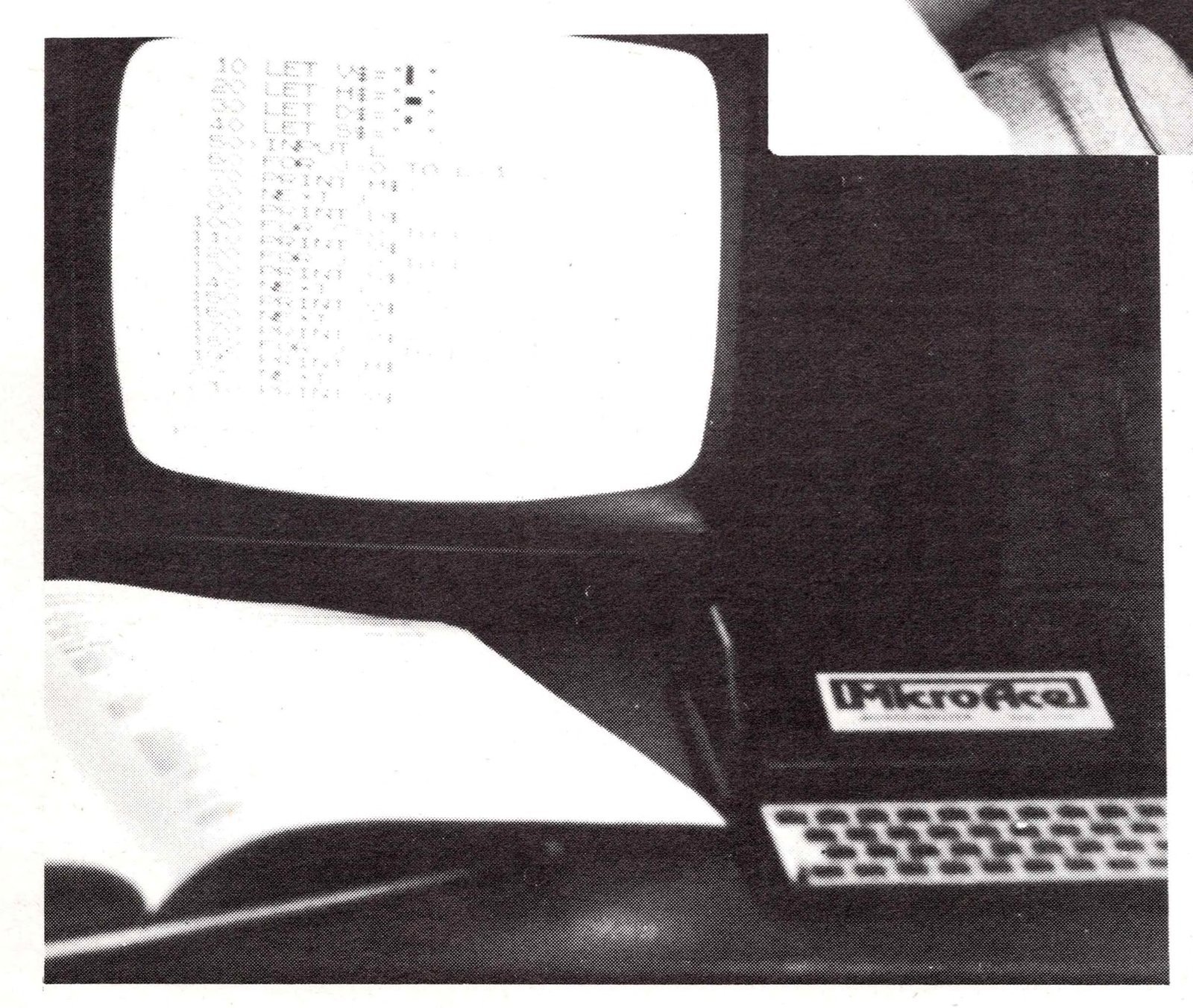
Now consider this. Today I sat down to build another personal computer, a MicroAce that retails for $169.00 (less than 9% of the cost of the IMSAI), and takes approximately 7 hours (less than 10% of the time) to build. It measures about 8-1/2″ X 7″ X 1-1/2″ and weighs in at 13 ounces.
But what do I get with the MicroAce? Well, let’s look at that for a moment. It comes with processor, cassette interface, pressure-sensitive keyboard, video interface (with built in UHF modulator so that it connects directly to the antenna leads on a standard TV set), power supply (an AC adaptor just like the one you use on your calculator that plugs into a regular 110 volt wall outlet), 2K of RAM memory and a 4K Basic in ROM. Basic? When we first built the IMSAI we couldn’t even buy a Basic that would run on it! The IMSAI had more memory and certainly more potential to expand (and, in fact, was eventually developed into an extremely powerful system), but in comparing what is available today versus what there was back in the “early” days of home computers, there is no question that the MicroAce is amazing.
I should mention that my background is in software; I am not a hardware person. Extensive exposure to the equipment has given me a reasonable understanding of how it works, but I am not an expert. The only experience I have had with building electronic kits is that with the IMSAI.
Okay, now that we’ve set the scene, let’s get down to the discussion of what it took to build this machine. The first phase of the project was to read through the manual. Upon opening the booklet I first saw a xeroxed sheet with a heading that said “Important— Read this and the last page in the manual first.”
Alright, this is a newly released product so I guess errata sheets are to be expected. The best way to handle an errata sheet is to transfer the corrections directly into the manual with a colored pen. Don’t be afraid to write in the book — remember, it is yours. This way you will not forget (or lose) the changes. One of the changes involved installing two jumper wires on the back of the printed curcuit card (PCB), but nowhere did it say when this should be done. Since they would likely be in the way during normal assembly, I noted in the instructions (on page 11) that this should be done just prior to inserting the integrated circuits (ICs).
Now to the assembly instructions themselves. Note that the manual is sub-titled “The Teach-Yourself BASIC Manual.” This is not particularly misleading. Of the 66 pages, the chapter on assembly takes 10; and that contains 4 pages on tips and component identification, 2 on board diagrams and 1 on a parts list. Much of the remaining 3 pages are either diagrams or precautions. The actual assembly instructions basically just say:
1. Install sockets
2. Install small discreet components
3. Install tape and power sockets, voltage regulator and modulator
4. Make tape and video cables (if necessary)
5. Insert ICs
These are indeed sparse assembly instructions. Now, I fully admit that the rest of the manual goes on to explain Basic to the novice in a very reasonable fashion, but it seems to me that a little more detail on the actual construction is called for (maybe even just a checklist by component type?). In any case, they do provide you with some very good information on both component identification and on many of the precautions that should be taken in the process of putting together the MicroAce (or any other digital electronic circuit board kit), including such things as how to avoid destroying static sensitive chips. I do hope you have some familiarity with the terminology, otherwise you may find the instructions confusing.
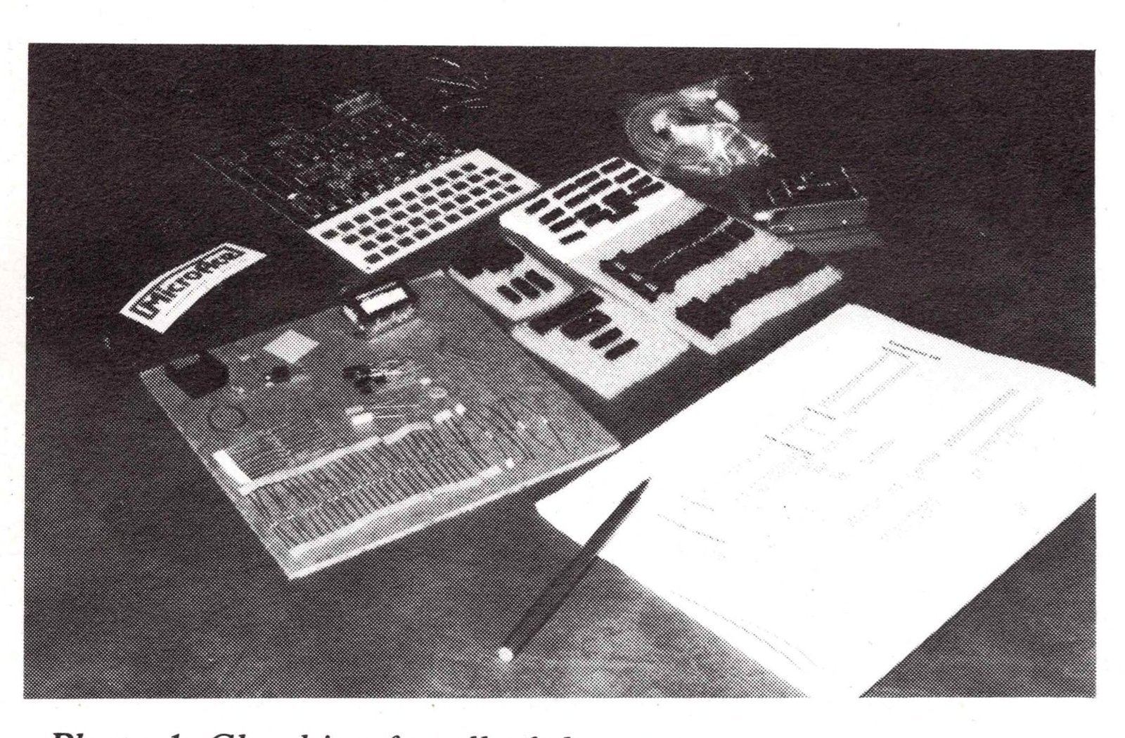
Having become familiar with the instrictions, I proceeded to compare the parts supplied against those in the component list. This was a relatively straightforward task since they provide an excellent section on parts identification, including a complete list of resistors, by number, with their color codes. Checking the parts off as I went along, and noting any discrepancies, I found I had 1 extra resistor, 1 extra socket and 2 missing diodes. Well the extras would obviously not be a problem, but the elusive diodes might.
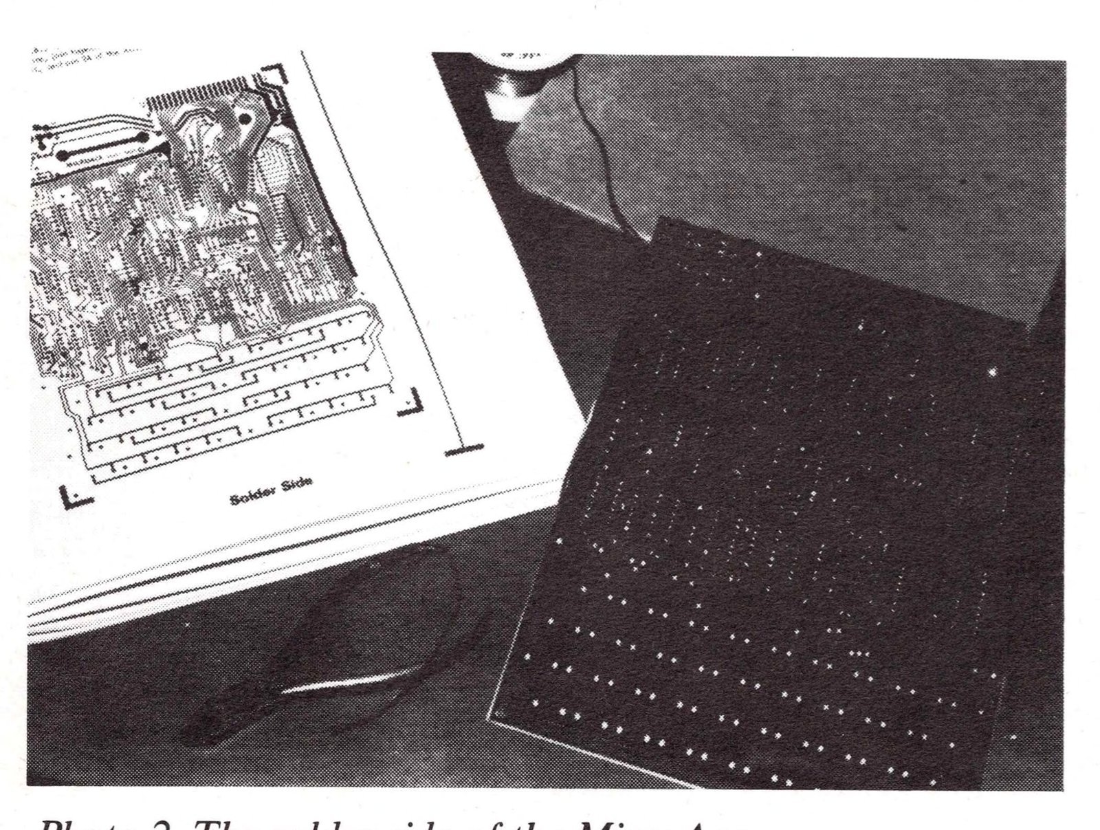
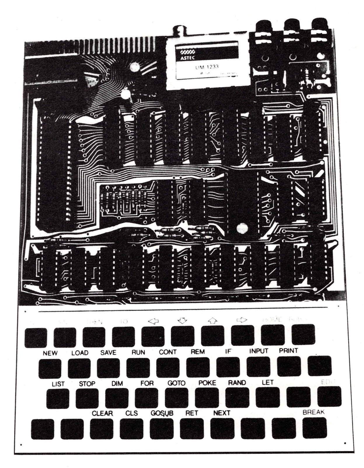
Since the next step was to locate the positions of all the parts on the board (using the component layout on page 7 of the manual), I decided to look first for where the diodes were located. Low and behold, I saw markings for only 9 of them, instead of the 11 indicated in the parts list. Encouraging. Maybe I wasn’t missing anything afterall. As a double check, I went to the schematic (pages 34-35) and once again could see only 9 diodes. It seemed safe to assume that the component list was wrong.
I found the rest of the parts easily. There was just one confusing marking on the board layout. Since this is a new release, it did not surprise me to find extra screenings on the board for parts no longer necessary. These were all clearly noted in the list of components. However, I noticed a symbol for a transistor (TR1) on the upper righthand corner. Once again I went to the schematic, but could find no indication of any transistors. With none supplied and no other mention of it to be found, I assumed it to be one more unused part, so I indicated that on my component list.
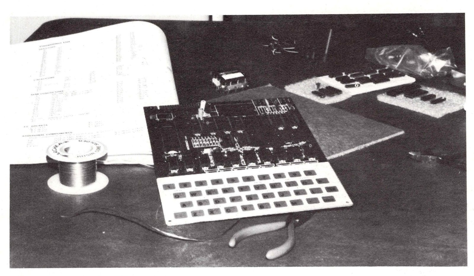
Now I was ready to turn on my soldering iron and begin. Following the instructions, I started with the sockets. This practice works well not only for efficiency of construction, but also because it means initial soldering is done on things that are not damaged when overheated. I found this reassuring since I was afraid I’d be a little rusty in this department. All went well. I was pleased to see that they had been very careful in the placement of markings on the board. Although things were somewhat tight in places, nothing was hidden as I put in the sockets.
The next task, according to the manual, was to install the discreet components. With no detailed instructions or checklist, I decided to follow the component list, checking off the parts as I put them on the board. Once again the component identification write-up turned out to be very useful, as it showed orientation markings for those parts that had to be inserted in a particular direction (the two electrolytic capacitors and the nine diodes). First I put in all the resistors (R1-R36), double checked their positioning, soldered them in place, clipped their leads and inspected the solder joints. I then did the same with the capacitors (C1-C16), then the diodes (D1-D9) and the crystal (X1).
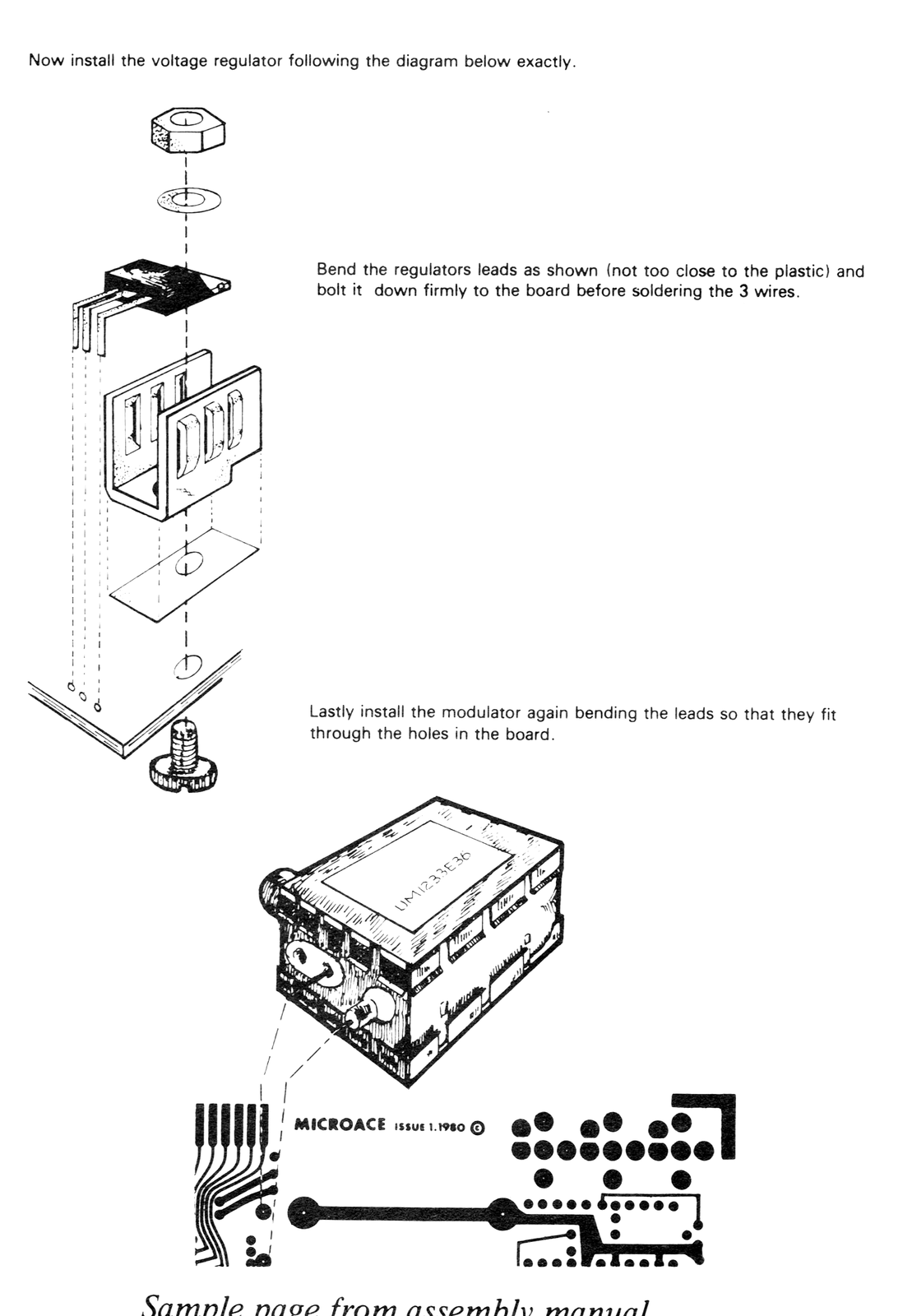
The instructions then call for installing the 3 tape and power sockets (not mentioned in the component list), the voltage regulator (U25) and the UHF modulator, in that order. Following the excellent diagrams in the manual, this was done with no problem. Then came the tape and video cables. The manual states that if you’re lucky (based on availability) they will come pre-assembled. I was not lucky. But since I had cables available from other equipment, I postponed this task for later. I do feel that if they are going to send unassembled cables, they should at least provide a diagram for their construction.
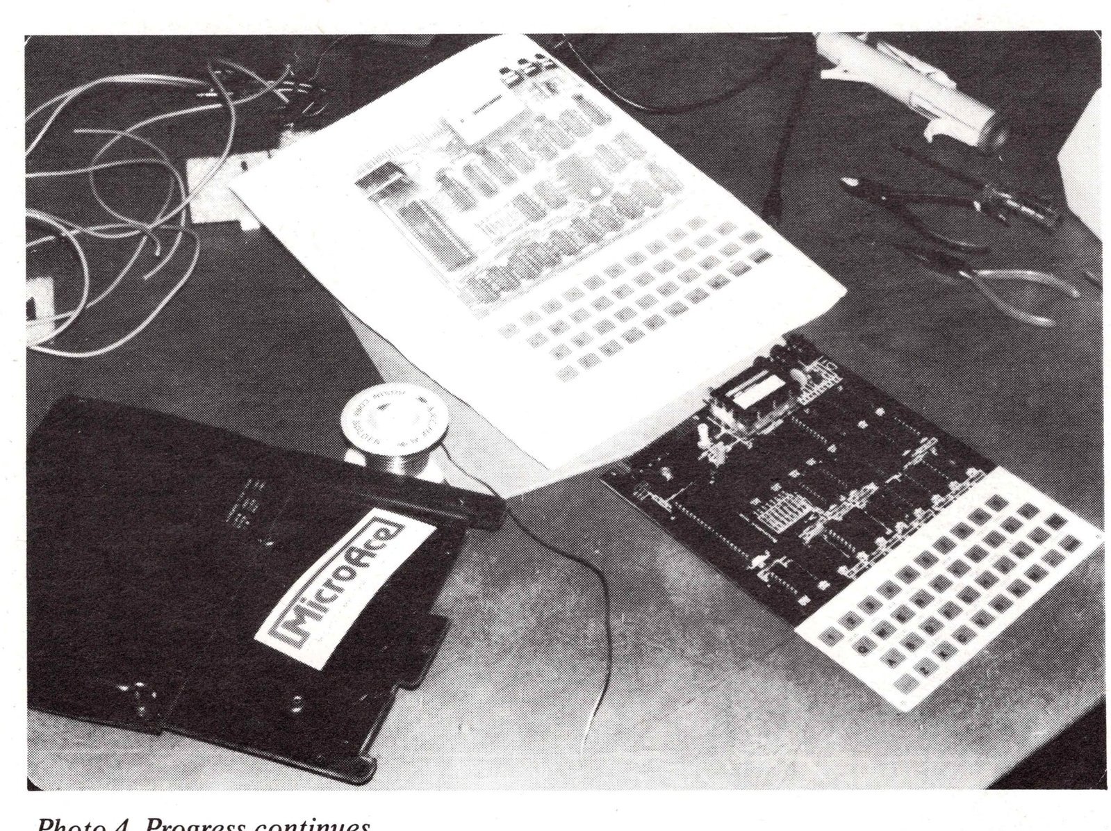
In any case, all I had left to do was the insertion of the ICs. Or did I? No, I had noted in my manual that this was the best time to install the two jumpers called for by the errata sheet. After doing that, I inserted the 24 ICs, being careful to follow all the precautions and tips mentioned in the instructions (except for earthing myself on a cold water tap; I discovered 5 years ago that working barefoot on a tiled floor eliminated the risk of static).
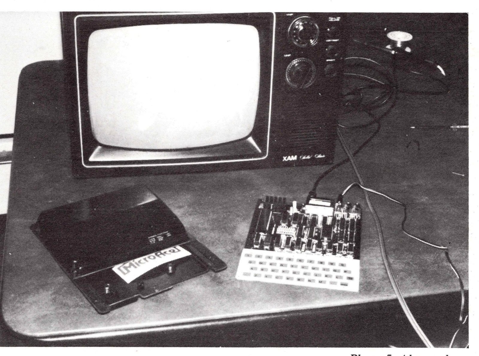
I now had a completed MicroAce computer. It seemed sensible to test it before putting it into its case, so the crucial moment had arrived. I hooked it up to my TV, plugged it in and there it was— a blank screen with a K in the bottom left corner. So far, so good.
Then I pressed a key. Nothing happened. Nothing. Well, it was time to start checking and re-checking the board. After spending quite some time doing just that, looking for misplaced or incorrectly oriented components, bad solder joints or bent under pins, I was getting quite discouraged. Yet I was determined to have a working computer. Sure, the kit comes with a terrific guarantee— for a flat fee of $20 you can return it to the company and they will repair it and send it back in perfect working order. But that might take a couple of weeks. I wanted to start using it immediately.
As I said before, I am not a hardware person, but I decided to look at the schematic anyway to see if I could pin-point, or at least isolate, the problem. I noticed immediately that the 8 diodes along the bottom of the board were a direct interface between the keyboard and the rest of the circuitry (going specifically to U11). I had checked those diodes a number of times already and was sure they were installed correctly. Checking them again reassured me that I was right.
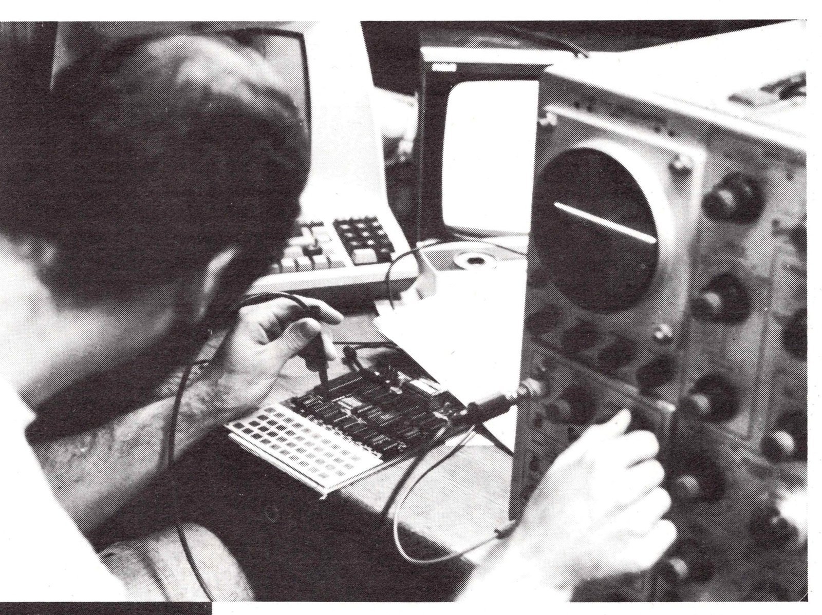
I won’t go through the whole frustrating story of the next few hours trying to track down the problem with a friend (who is a hardware person and who also checked the diodes). Needless to say, in the end we discovered that the diodes were in backwards. What had appeared to be a yellow diode with a green band on one end, was in reality a clear diode with a narrow green band on one end and a very wide yellow one on the other. What can I say but that I hope someone can benefit from my mistake.
Anyway, at that point (about midnight), it didn’t matter. My MicroAce worked— that was exciting. Forgetting all the earlier frustration, I put it in its case and sat down to a couple of hours of joyous programming.