Are you tired of having to use the 2068’s ON-OFF power switch to reset the computer? Read on, there is a solution.
Do you have & Larken disk system and also one common AC power switch to turn on your computer, disk drive, disk controller, monitor. monitor, and all other peripherals? If you do, you’ve no doubt experienced the inconvenience of having to shut your computer OFF and then ON again in order to initialize properly. Read on, for there is a solution.
Do you have a 2068 with a wired-in Spectrum ROM and are having some problems with the computer not initializing positively on the Spectrum ROM without having to turn the computer’s power OFF & ON a number of times? There is a solution!
The solution is very simple and would cost less than $6.00 in our lowly Canadian Dollars.
If you have one or all of the above problems, install a RESET push-button (P.B.) and a small 10 mfd. tantalum capacitor and your problems are resolved.
INSTALLATION
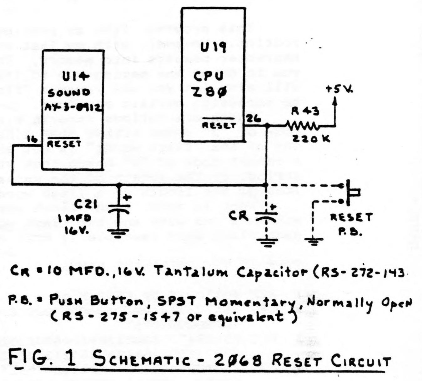
The 2068 has an existing circuitry that automatically resets the computer whenever the power switch is turned ON. Fig.1 shows this circuit in a simplified schematic form. The solid lines along with resistor R43 and capacitor C21 are the existing reset circuftry. The dotted lines show the required additional components—the pushbutton (P.B.) to provide the means for manual RESET (whenever you wish) and capacitor CR to provide positive initialization on power up.
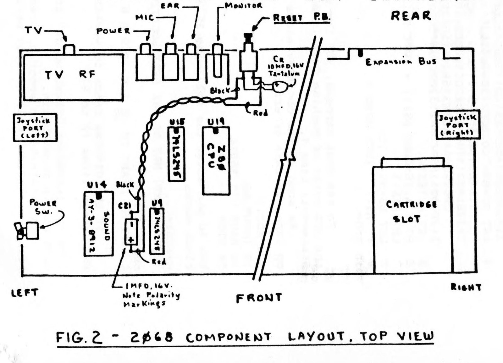
FIG.2 shows the suggested placement of the RESET P.B., capacitor CR and wiring. To install these, you will have to remove the top of computer (containing the keyboard).
Drill a 1/4 inch hole on the rear lip of the portion of the computer and mount a mini P.B. A preferred location is near the monitor jack, but leave sufficient space for convenient push-button finger reset action.
Use color-coded wire (black & red preferred) and solder one end of these wires to the protruding leads of the capacitor C21. Make certain that the red wire is soldered to the positive lead of C21. Twist the wires and run the wires neatly to the P.B. Connect the wires to the P.B. leads but do not solder. Now connect the 10 MFD. capacitor CR to the respective leads of the push-button, making certain that the positive lead of the capacitor CR is connected to the push-button lead containing the red wire. If this is correct then solder the wires and capacitor CR to the push-button. This completes the installation.
Image Gallery