Authors
Publication
Pub Details
Date
Pages
The Faint-of-Heart Zone
Stay away from advanced video modes at any cost! Who needs them? Besides, what we can already do is all anyone really needs.
The screen is divided up into 24 rows of 32 characters, each of which can have 8 ink and paper colors plus bright and flash attributes. In addition, writing characters can be done using exclusive OR logic (useful for cursors), ordinary OR (useful for overprinting), AND (for selective erasing), and other modes for transparent ink, paper, negation and contrast.
In graphic mode, there are 176 rows of 256 dots (pixels) which can be plotted and drawn. Even though colors can be used, they apply only to whatever character space in which work is being done. Planning is required to avoid “bleeding”. Creating a graphics cursor is challenging, but rewarding.
Color blind people become irritated when the use of color interferes with their use of a program. Politely, the answer is to use color only for decoration, but this cheats others out of the program enhancements that color makes possible. The best way is to have separate programs for monochrome and color.
The Somewhat-Daring Zone
A limit of 32 characters per line makes it difficult to do word processing. Fear not! The TS2068 has an advanced video mode which increases horizontal pixels from 256 to 512, allowing 64 normal (or more if special) characters to appear per line. The BASIC commands for writing to the screen must be supported by new routines, either rewritten as with “64”, or in high memory as shown in the technical manual. Color is available, but applies only to the entire screen. Bright and flash generally produce poor viewing conditions.
Graphic mode is possible. Its primary use would be for word charts and line drawing in support of word processing.
Though better than 32 wide for word processing, there is still not enough room on screen to accommodate a graphic printer line unless more than one screen line is used per printer line.
The use of printer “windows” mapped to the screen, where they can be written to at will, forms the basis for drivers to access printer graphics. The same applies to 32 wide screens, so printer drivers should work in both modes.
Experience shows that 64 wide mode has no advantage over 32 wide when it comes to “windowing” and desk-top-publishing unless larger than screen windows are required, and tiling is not an acceptable option.
The Devil-May-Care Zone
Those who are somewhat-daring use programs written for them, or a cartridge. Both save the user the trouble of learning how their programs work. What they do is not in the general users’ manual so there is a learning curve.
Going higher on the learning curve reveals new horizons to the adventurer — high resolution color!
Because adventurers aren’t that rare, it descends upon those of us with programming skill, the responsibility to develop tools for them; as happened with “64”. The rest of this article will be devoted to describing that task, beginning with historical considerations.
The Original Cheap Monitor
The console is the computer’s interface with you, consisting of a keyboard and monitor. Though usually a video tube, a printer was often used for logging status messages (works for the TS2068 too, hint). For home computers, the most easily obtained monitor is your TV set.
TV standards limit how good a picture you can get. Detail improves with increased bandwith (the size of channel assigned by the FCC for broadcasting). For black & white sets this came out to be about 400 pixels per scan line. This becomes less for color TV because the channel has to be divided up among colors. Assignments are unequal. Intensity gets the most, blue next, then red (oversimplified, but you get the idea). If you look closely at the TV screen, you can see that red areas smear out several pixels referred to intensity.
To make a remarkably affordable, yet powerful home computer, Sinclair designed a video driver with color TV as the monitor. With no monitor or printer to buy, what a deal! As options, RGB monitors and a special printer could be attached.
Anyone trying to display colors at too high a resolution has found out about blurring. For acceptable results, more than one adjacent pixel must be assigned to a color. A 4*4 checkerboard character gives much better results than an 8*8. An RGB monitor does not have this limitation.
There is a “bug” in the TS2068 caused by two crystals not being synchronized with each other. Rippling color bands are caused by the phase difference.
Advanced Color Mode And TV
At first, the advanced color scheme for the TS2068 is hard to understand.
Other computers, with expensive monitors, have screen display formats tailored for specific applications.
Those modes which are character oriented work the same as the TS2068.
Graphic modes are pixel oriented — e.g. each screen pixel has a number associated with it. The number occupies a number of data bits called depth. One byte can hold one pixel of depth 8, two pixels of depth 4, etc. “TRUE COLOR” uses 24 bits, 8 for each of R, G & B.
As you can see, full screen color pictures have tremendous memory needs. Within the memory restrictions of the TS2068, a remarkable compromise was made, consistent with using TV as the monitor. There are two memory bytes for each byte written to the screen, making pixel depth 16/8; a value which could provide four colors on an IBM CGA adapter, but not the TS2068. It takes two bytes to display two colored dashes of four pixels. One in D_FILE1, a nibble of INK followed by a nibble of PAPER set up in advance to make two dashes, and one in D_FILE2 to define 2 colors. Using four pixels per color does away with smear, but allows only 64 dashes per line.
Colored dashes on screen can be combined in various ways to obtain more colors, but only one technique is sufficient. Two vertically aligned dashes blend their colors as viewed, so two dashes can define 36 colors instead of just 8. (64 combinations, but many are reverse order duplicates.)
From here on, a colored vertical dash pair is what we are talking about when we say “bixel”, appropriate because bixels (pairs) always come in pairs.
The bytes defining them also come in pairs. We will call the first byte scan#0 and the second scan#l because that is how they will be used. ScanO defines the upper half colors of both bixels. The lower halves are colored by the second byte. These are written to D_FILE2. D_FILE1 was prepared in advance by filling the image frame with 00001111 to make dashes.
scan#0    scan#l     bixels on screen
OOaaaccc             ....aaaacccc....
         OObbbddd    ....bbbbdddd....
A bixels file can be of any size. It can be panned if larger than the screen. For the moment let’s consider a file (picture) that fills the top half of the screen. It will be 64 bixels wide by 48 high and consist of 3,072 bytes.
Even bytes go to even scan lines, odd to odd. 32 byte pairs are written before going on to the next scan line pair. An algorithm for computing sequential addresses (starting at 24576) is simple and easily written.
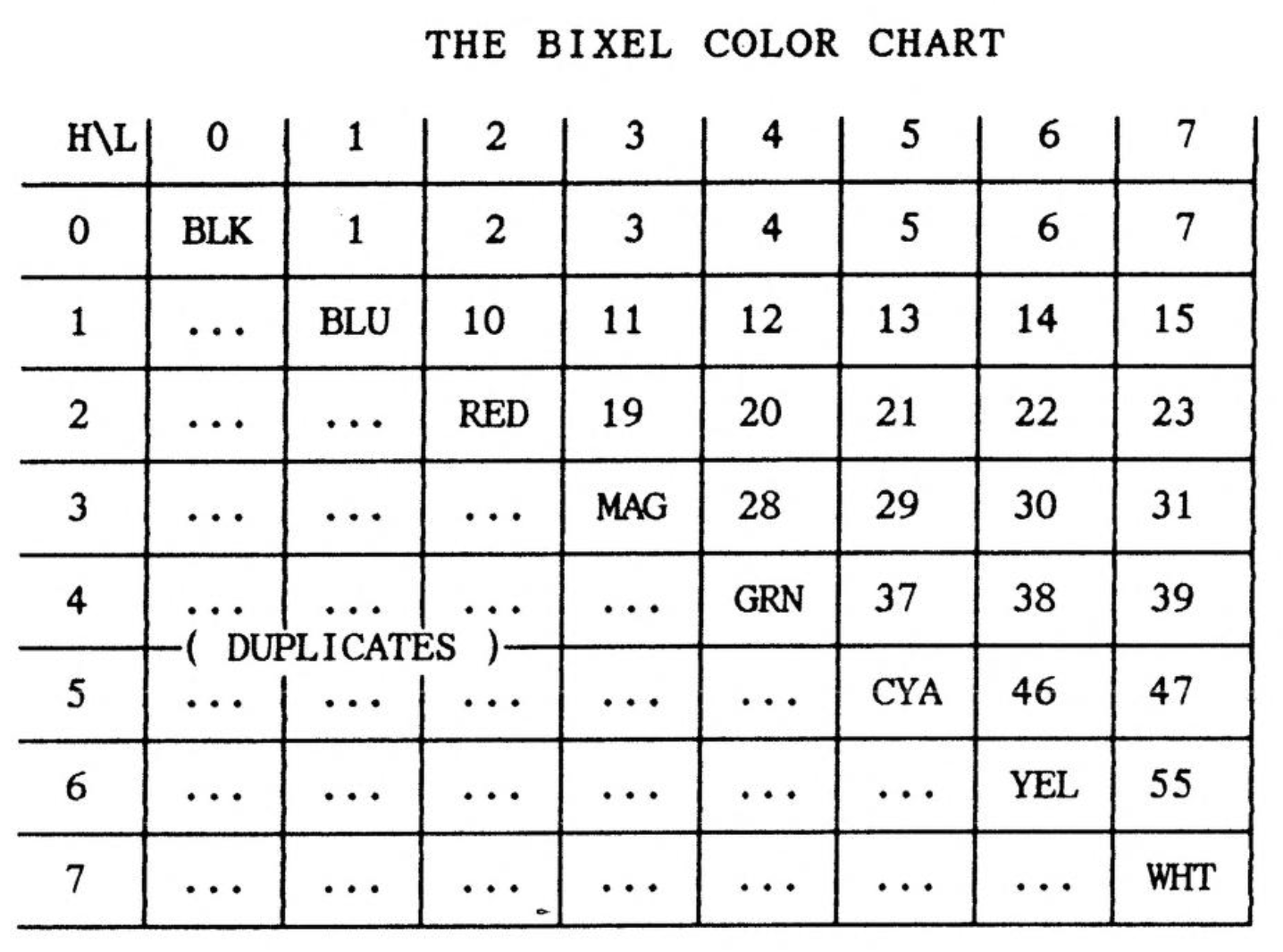
This table shows all possible bixel colors and labels which could be used to decribe them. The area […] holds duplicates of colors to the upper right. There are 36 different, ignoring the possible use of Bright. (If used, both Bright and Flash must apply to both bixels of a pair. They won’t be used here.)
Remapping Memory
Advanced video uses D_FILE2 in CHUNK3. On startup, BASIC overlaps (shadows) D_FILE2. BASIC is allocated 38,655 bytes. This drops to 31,743 when using advanced video modes. Running in Spectrum mode allows even larger programs to run. Little effort has been spent writing programs that use overlays and/or bank switching to let large programs make better use of memory, Oliger DOS makes overlays relatively easy, so somebody out there, get on the ball.
BASIC conflicts with the SCLD video processor when shadowing CHUNK 3 (Spectrum even more so). Everything slows down, BASIC runs faster when memory is remapped even when advanced modes aren’t being used. Contrary to what the tech manual implies, use shadowing only when you really must have that last piece of memory. ALWAYS use remapped memory If you can.
The routines in EXROM for remapping memory have some problems, but can be used with sufficient care. There are errors in the jump and fix tables which you don’t normally bump in to. A much simplified version of the access routine in the tech manual is available. Once called, there is seldom any reason to reverse it
An interesting possibility for storing machine code exists when A_FILE1 (768) and/or A_FILE2 (768) are not being used for video.
The most important thing to remember about video modes is that there is absolutely no functional connection between memory mapping and video modes. You can change video modes any time you please without crashing anything. Of course, if memory has not been remapped first, there are going to be some awfully weird looking screens. Once memory has been remapped, BASIC is all you need to run your video mode applications.
Bixel File Structure
Graphic files usually have a header defining what they are to interpreters that handle many file types. Programs expecting only one file type can dispense with a self defining header in some cases but other programs cannot.
The first byte of the file tells the interpreter something. It may not be enough, but it’s a start. The first byte of a bixel on screen is OOpppiii, followed by OOPPPIII.
Notice that the first two bits, which normally represent FLASH and BRIGHT respectively can be used for control purposes in a file without displacing data. Setting bit 6 high could signify the start of a row. Setting bits 6 and 7 high could signify the end-of file (EOF). Reading through a file, you can count the columns and rows for the file and store them. If the file is bigger than the frame, a common default is to display the upper left corner of the picture, and enable a panning utility.
At least two more bits are available for control because bytes always come in pairs. Odd numbered bytes could have bit 6 set for EOF instead of the even byte bit 7. Then all characters would pass a bit 7 filter, but all values from 0 through 63 represent valid data, so ASCII control characters would be present. This would pose a problem for modem transmission of files.
Borrowing a technique from RLE, we might add 32 to all data to avoid having to deal with control codes. Valid data bytes would then be from 32 to 95. It looks like we have a winner! Using a header, we encode our values instead of RLE pixel counts. Values greater than 95 cannot represent valid data, so they can be used to insert special bytes into the data stream. A file identifier of “ts” (116,115) is nice. Beyond that, ASCII command codes can serve to delimit rows and provide EOF.
Video Editors
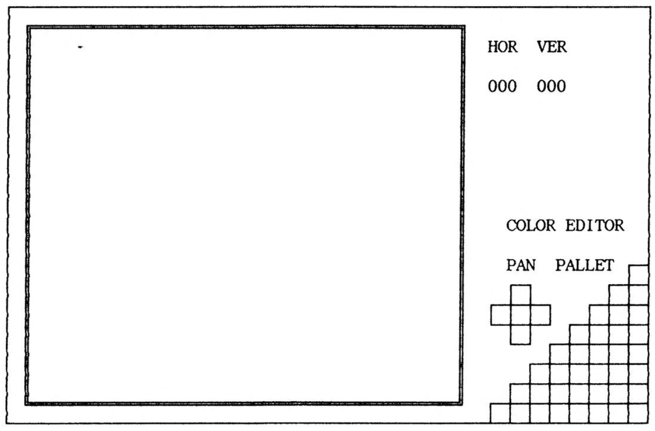
Making a cursor visible on a full color screen in advanced video mode is not as easy as it sounds. Blinking is the only sure way. The trick is how to make only one bixel blink instead of two. The answer is to operate the blink from the editor, not the SCLD. The blink must be three steps, true color, all white, all black and repeat .
Somewhere on screen should appear a pallet of all 36 colors, so the cursor can be used to select a color for painting with the press of a button.
When not selecting, the cursor position color should show on the pallet.
Somewhere on screen should appear the file array coordinates of the upper left corner of the viewing frame.
Command buttons should be available to pan the image in the duplicate color area of the pallet display.
Other functions are best handled using the keyboard.