
The whole idea of experimenting with a “TURBO Switch” came from reading the book “EXPLORER’S GUIDE TO THE T/S 1000” by Mike Lord. On page 58(1) of this book under the heading “Keyboard Scanning” he tells how the system variable MARGIN may be changed from 55 to 31 by taking pin 22 of the ULA chip HIGH or LOW. This is supposed to be of use to the computer manufacturer to enable the T/S 1000 to be used in either the USA which uses 31 blank lines at the top and bottom of the screen, or in the UK which uses 55 blank line. The book also states on page 52(2) under the heading “NMI Handler” that “When in the SLOW mode the ZX81 uses the time occupied by these blank lines to carry on with your program”.
So I thought if I increased the number of lines on my T/S 1000. I might increase the speed of program execution. And it works well. I use direct video and have not tried it using the RF modulator, but if you use direct video I think you will have success from the modification.
To test the speed of program execution I use the following BASIC program:
10 FOR N = 1 TO 500
20  NEXT N
30 PRINT "FINISHED"
With pin 22 HIGH the computer takes 20 seconds. With the pin low, the program takes 28 seconds. (About a 28% increase in speed. Don). This is a considerable increase in speed. One might ask “Why have a TURBO Switch?” Well, when I use my WORD* program (word processor) at the “TURBO” speed the cursor blinks at about twice the normal rate and does not seem to miss keys as it did in the past, and when playing games I use the slower speed so that I can get a higher score!
When using the higher speed I find the monitor screen is filled with lines from top to bottom, when using the slow speed I find a blank screen at the top and bottom 1/2 inch of the screen. I can switch from “TURBO” to normal at any time without any crashes.
Lastly, how is the modification carried out? You have to take the T/S 1000 circuit board out of it’s case and locate resistor R30 which is located between the ULA chip and the regulator heat sink. It should have the colors Brown Black Brown.
Using a soldering iron, lift the left hand end of the resistor clear from the circuit board hole. Also locate resistor R38 which is four resistors down from R30, and solder one end of some two core cable to the left hand end of R38, which should be a 5V rail. To the raised left hand end of R30, solder one end of a 1K 1/4W resistor. Bend the resistor upwards and solder the other end to the right hand end of R34, which is a 0V rail. To the junction of R30 and the added 1K resistor solder the other core of the two core cable. To the other end of the cable solder a switch of the single throw single pole type.
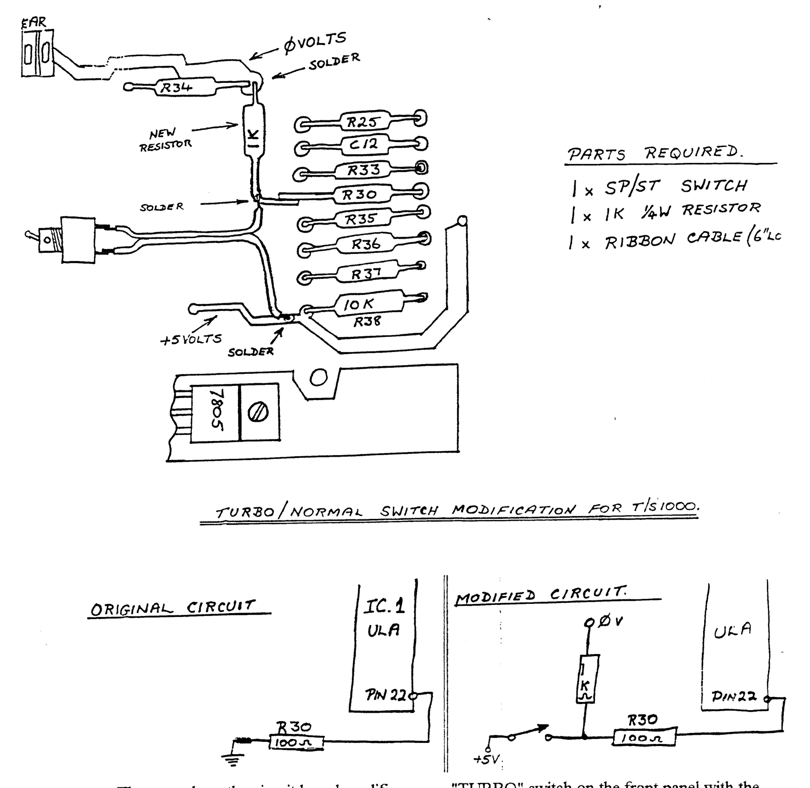
PARTS REQUIRED.
1 x SP/ST SWITCH
1 x 1K 1/4W RESISTOR
1 x RIBBON CABLE (6″L[illegible]
That completes the circuit board modification. Try connecting a multimeter at the solder connection between R30 and the 1K resistor. and ground. When the T/S 1000 is powered up, the “TURBO” switch should change the voltage from nearly 0Volts to nearly 5Volts. and if you have your monitor connected you should see the screen flicker.
The switch should be mounted somewhere convenient, accessible from outside the T/S 1000. I have my T/S 1000 mounted inside a steel chassis and so I mounted the “TURBO” switch on the front panel with the words “TURBO” and “NORMAL” along side the switch. Try ENTERing and running the program that I LISTed earlier and see the difference the switch makes. ENJOY!
(1)(Page 58) KEYBOARD SCANNING
This is a fairly straightforward subroutine which is normally called from the Main Display routine, but which can equally well be used by your machine language programs.
It returns a code in the IIL register pair corresponding to the key pressed, or FFFF if no key was pressed. It also loads the System Variable Margin (4028) with the correct number of blank lines needed at the top and bottom of the picture; 55 for U. K. machines, 31 for the U. S. A. models, by detecting whether pin 22 of IC1 is strapped to 0V or not.
(2)(Page 52) NMI HANDLER
As each horizontal TV scan line is completed in 64 micro-seconds, it takes 24 X 8 X 64 micro-seconds – which is just over 12 milli-seconds – to output the complete 24 rows of characters displayed in each TV frame. But, to synchronize the TV set properly, each frame must last for 20 milli-seconds (16.7 milli-seconds for the U. S. A. model), so additional – blank lines are needed to fill in the top and bottom margins of the picture, before during and after the frame synchronization pulse.
When in the SLOW mode, the ZX81 uses the time occupied by these blank lines to carry on with your program. But, to keep track of the time, it is interrupted by the SCL chip every 64 micro-seconds. The non-Maskable Interrupt is used for this function, and calls the routine starting at 0066 hex. 0/0.