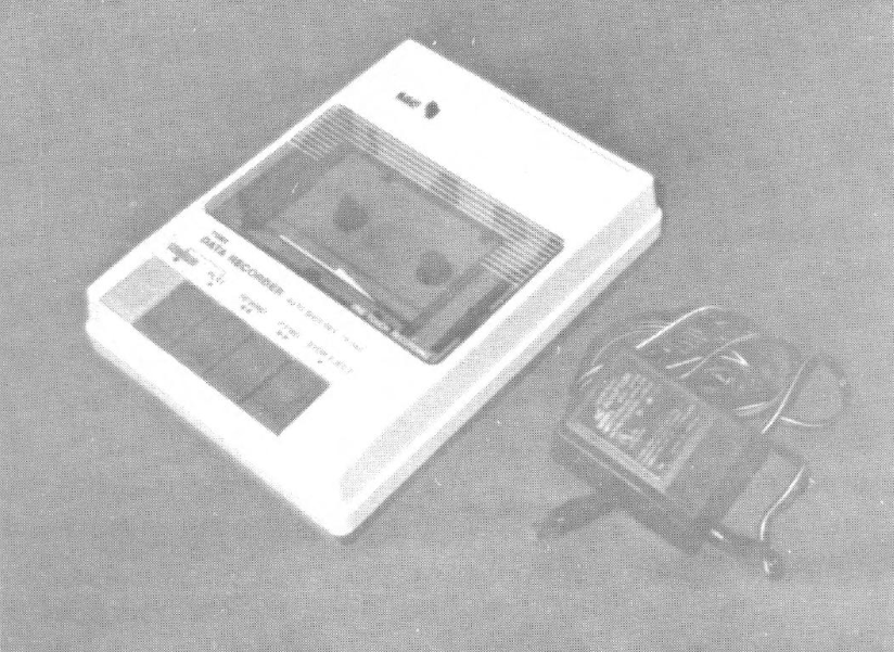
While looking in a Video Concepts store the other day, I came across some old computer accessories they were selling off and found some “Tomy Tutor” data recorders they were dumping at $3 each. The recorders come with a power supply and have a tape counter and speaker to monitor what you SAVE or LOAD. Figuring I could not go wrong, I bought two and took them home to try out.
Much to my disappointment, they did not have enough volume to LOAD a tape. There are no controls to fiddle with, so I went inside to see what could be done toimprove the gain of the circuitry.
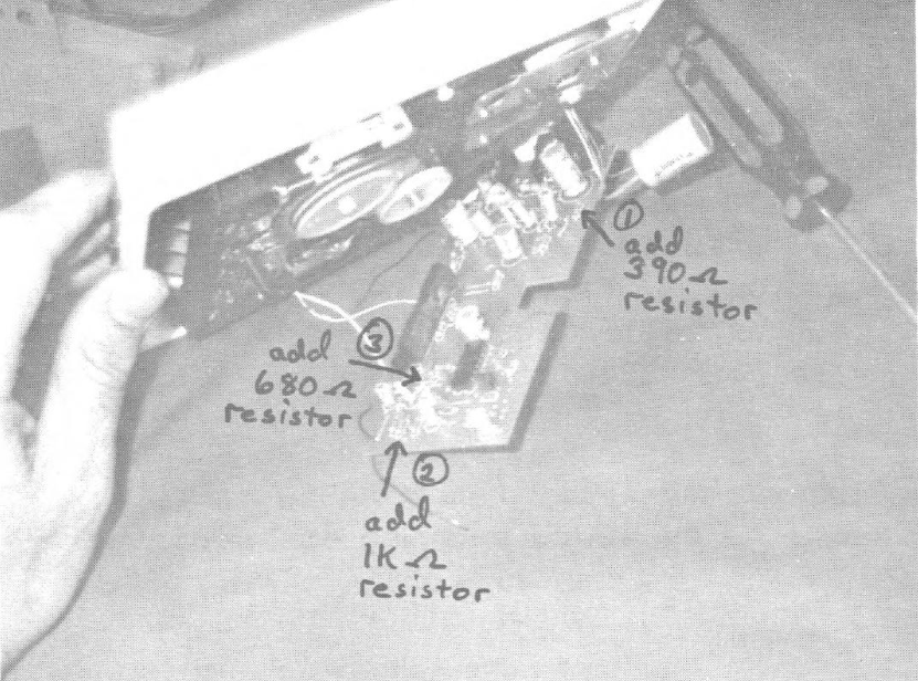
After many trials and errors, I finally discovered what did what and determined the changes that were necessary to make it work. The easiest way to make the changes was to piggy-back some extra resistors. Carefully remove the bottom cover and two screws holding printed circuit board (and shield) in place. Gently pull away the circuit board and put into position as in photo so you can see the components.
From the photo, follow the arrows to first a resistor marked red-black-red-gold (2000 ohms) and piggy-back a 390 ohm resistor (orange-white-brown-gold or silver). Second, find the resistor marked brown-red-orange-gold (12000 ohms) and piggy-back a 1000 ohm resistor (brown-black-red-gold or silver). Third, find the resistor marked grey-red-red-gold (8200 ohins) and piggy-back a 680 ohm resistor (blue-grey-brown-gold or silver).
Not visible in the photo is a resistor just behind the connector marked “IN” labeled yellow-violet-yellow-gold (470,000 ohms). Piggy-back a 100,000 ohm resistor to this one (brown-black-yellow-gold or silver). Also, there is a resistor right next to that last one marked red-red-brown (220 ohms). Short this one out with a piece of wire. These last two modifications may not be needed on some computers. Be careful while soldering these connections so as to not cause loose solder connections on the bottom or solder bridges to adjacent traces.
Once you have made these and made sure that everything is right, re-assemble for test time. Connect the “mic” plug to the jack marked “IN” and the connections “ear” plug to the jack marked “out”. LOAD your favorite tape to try it out. You should be able to hear the data as it loads. One thing you may notice as it loads is that the pitch is higher. This is because the tape speed is faster than a normal cassette recorder. That means that your pre-recorded programs will load faster!
Since using this recorder, I have had no problems saving and loading tapes — no controls to worry about. It seems to be more reliable than my old die-hard Panasonic recorder. It is impractical to use this with the TS 1000 or 1500 due to the difference in motor speed (they won’t lock on to the different data speed like the 2068 (and Spectrum) does.
To find them in your area, check any stores which carried the computer. It was geared more towards young children, so check with toy stores and also with pawn shops. Be sure and not mix-up the power cables – they are the same type.
Products
Media
Image Gallery