
1. Introduction
When circumstances combine innovative technical ideas with an economical design and market opportunity, some interesting things begin to happen. In 1980, Clive Sinclair was not yet a household word and was perhaps better known for his digital watch and calculator than his ZX-80 personal computer. But Sinclair decided the time had come for an affordable and easy to use mass produced version of the ZX-80 with floating point math and a non-flicker display.
The ZX-81 was born and as they say “the rest is history”.
A key to the economical design of the ZX-81 was the video system. Not only was it cheap to manufacture, but the ZX-81 video circuit turned out to be versatile with capabilities well beyond the designers original goals.
2. ZX-81 Display Basics
The standard ZX-81 video screen displays 24 rows of 32 characters. Every character has height of 8 scan lines and a width of 8 pixels. The characters to be displayed are located in a block of memory called DFILE. The set of 128 displayable characters includes 64 normal (white on black) uppercase only letters, numbers, symbols and graphics characters and their inverse (black on white). The ZX-81 character codes CHR$ 0-63, CHR$ 118 and CHR$ 128-191, are non-standard (not ASCII). A set of token codes is also used for keywords, functions and commands but these are always expanded to the displayable characters before printing to DFILE. The DFILE is formatted starting with the Sinclair equivalent of a Carriage Return (CHR$ 118) followed by up to 32 CHR$ codes, this repeated 24 times and ending with a CHR$ 118. CHR$ 118 is the opcode for the Z80 HALT instruction for reasons which will be explained later.
All other character codes are illegal and if loaded into DFILE will generally cause a system crash. The collapsed DFILE is used in the 1K and 2K basic ZX-81 to optimize screen memory requirements. When empty a collapsed DFILE consists of just 25 CHR$ 118 codes. Each line is expanded when characters are printed to that line. When equipped with 4K or more of memory, DFILE is initialized to the fully expanded format with 24 lines of 32 CHR$ 00 (space) characters and 25 CHR$ 118 line termination characters.
The character codes are not displayed directly but rather are used as address pointers to a ROM video pattern table. The ROM pattern bytes are addressed by a combination of the character code in DFILE and the ZX-81 hardware and is loaded into the video shift-register. Bit 7 of the character code is used by the video hardware to invert the pixels as they are shifted out of the shift-register. The display on the screen is generated by the serial bit stream of pixels, a video shift-register which turns the TV CRT electron beam on and off as it scans the phosphor coating on the inside face of the picture tube.
A fully expanded DFILE with 24 lines of 32 characters per row and 8 pattern bytes per character displays 6144 pattern bytes or 49152-pixels per screen.
3. SLOW Mode Video
In the SLOW mode, the CPU is multitasking between video and program execution. About 80% of the CPU time is allocated to video and keyboard service routines and only about 20% of CPU time is available to execute the application program. In fact, the CPU time is divided in four distinct task blocks per TV frame as shown in the table.
1. Tasks are switched using a Non Maskable Interrupt (NMI) generator to call an NMI service routine which controls task switching from the asynchronous application program to the real-time video routines.
1. VSYNC, frame count and keyboard     NMI off
2. Blank lines/application code        NMI on
3. VIDEO DISPLAY routine               NMI off
4. Blank lines/application code        NMI on

       SLOW Mode CPU Task Table
Each task can be described in more detail as follows;
1. During the vertical sync interval, when no video is actually displayed, the CPU executes a fixed length VSYNC routine which increments a FRAME counter, reads 8 rows of keyboard data together with the 50/60Hz mode bit. Any I/O read operation with AO low (i.e. FE) addresses the ULA keyboard port. It also causes the ULA to start the vertical sync pulse by clamping the video output to the 0V sync level and simultaneously applies a reset to the ULA 3-bit line counter (LCNTR). After the all the keyboard data is processed (400µs later), the CPU executes an OUT FF, A (any OUT will do) which restores the ULA video output to the normal “white level with horizontal sync pulses” and releases the LCNTR reset. At the end of the VSYNC routine, the number of blank lines to the start of the live display are determined from the system variable MARGIN (50/60Hz). Then the NMI generator is turned on and the CPU registers are switched back to the application task.
2. While the CPU executes the application code, the CPU is interrupted every 64µs by the NMI generator at the same time the ULA generates a horizontal sync pulse. The NMI routine increments a blank line counter in A’ and returns if there is more time left for application code execution. When the blank line counter is incremented to zero, the NMI routine turns off the NMI generator and switches to the VIDEO DISPLAY routine through a pointer in the IX register.
3. The video display routine sets up the display file pointer, the row and line counters and enables INT and JP(HL), to the start of DFILE + 32K. Each character in the DFILE is interpreted as a NOP instruction except for the N/L character which terminates the line. At the end of each line, the INTservice routine updates the row and line counters and returns to execute the remaining lines. After 192 lines, the video display routine ends by turning on the NMI generator and the CPU switches back to execute the application code.
4. As before, during the top blank lines, the NMI routine counts the number of blank lines remaining. At the end of the bottom blank lines, the sequence repeats when the NMI service routine switches back to the VSYNC routine.
4. FAST Mode Video
In the ZX-80 comparable FAST mode, the CPU executes either the video routine or any other program but not both which causes the familiar flicker of the display when switching between these tasks. When the application program is running, it is executed using 100% of the available CPU time. Only if the application program is STOPped (in the command mode) or waiting for a keyboard INPUT, or in PAUSE mode is the video is displayed. The video hardware is activated in the same way as the SLOW mode but NMI is always off. In addition, the blank lines at the top and bottom of the screen are also generated in software making the ZX-81 ROM fully comparable with the ZX-80 hardware.
5. ZX-81 Video Hardware
The ZX-81 video hardware consists of the Z80 CPU, ROM, RAM and the larger part of the ZX-81 Sinclair Logic Chip (the ULA) as shown in Fig. 1 with all relevant connections including the isolation resistors R. For simplicity only the 2K RAM is shown. The ULA contains a 6.5 MHz crystal oscillator and a frequency divider which generates horizontal sync pulses at the video output and NMI pulses on the NMI output. The HSYNC . and the NMI outputs can be controlled with the following I/O operations.
1.   OUT FD, A - turns off the NMI generator.
2.   OUT FE, A - turns on the NMI generator.
3.   IN A, FE - turns off the HSYNC generator. (only if NMI is off)
4.   OUT FF, A - turns on the HSYNC generator.
The ULA video output switches between 3 voltage levels. It is normally at the +5V white level for blank lines. Characters patterns are displayed as black pixels when the level is +2.5V. The narrow horizontal sync pulses and wide vertical sync pulses are 0V level as shown in Fig. 1 waveform. These logic levels are reduced with a resistor divider to 1V, .5V and 0V (UK/US) at the input of the TV RF modulator.
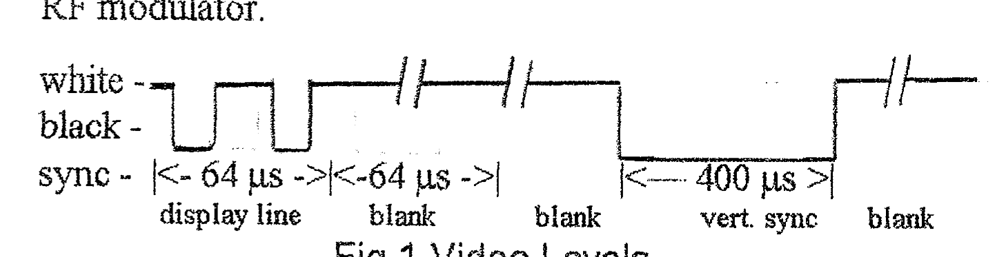
The HSYNG pulses are 5 µsec. wide with 64 µsec. between HSYNC pulses. The VSYNC is 400 µsec. wide with 16.6 msec. or 20 msec. between VSYNC pulses.
VSYNC is used to synchronize the TV vertical oscillator and start the raster scan at the top of the screen. This occurs when IN A, FE (used for scanning the keyboard) clamps the video output to the SYNC level. 400µsec. later OUT FF, A releases SYNC to enable the 64 µsec. HSYNC pulses. The HSYNC pulses continue to be generated independent of the CPU until the next VSYNC. The CPU executes the application code during the blank lines at the top and bottom of the screen while the NMI generator interrupts the CPU every 64 µsec. and increments a blank line counter to determine if it is time for the VIDEO DISPLAY of VSYNC routines.
6. ZX-81 Character Video Hardware
The Sinclair ZX-81 character display generator consists of the Z80, ROM, RAM and the larger part of the ZX-81 Sinclair Logic Chip (the ULA) as shown in Fig. 2 with all relevant connections including the isolation resistors R. For simplicity only the 2K RAM is shown.
