March 1993
It has taken me awhile, but I finally completed a working RS-232 interface. The design is based, in part, on the Z-SI/O board that is familiar to most 2068 owners. I simplified the design somewhat by using a 74LS4060 oscillator/divider chip to generate the baud rates and a MAX232 chip to convert the data output from ttl to serial, replacing 5 chips and a voltage regulator. The interface was designed for communication between the ZX81 or 2068 and another computer. At rates up to 4800 baud handshaking between machines is not necessary to ensure a successful transfer and therefore was not implemented. That being the case, this interface may not be suitable for connection to a serial printer or modem though it may seem to work. If enough interest is shown, I can change the design to provide full handshaking or change the serial standard from RS232 which will work over a distance of about 50 ft to RS422 which can transmit serial data over much longer distances.
CONSTRUCTION
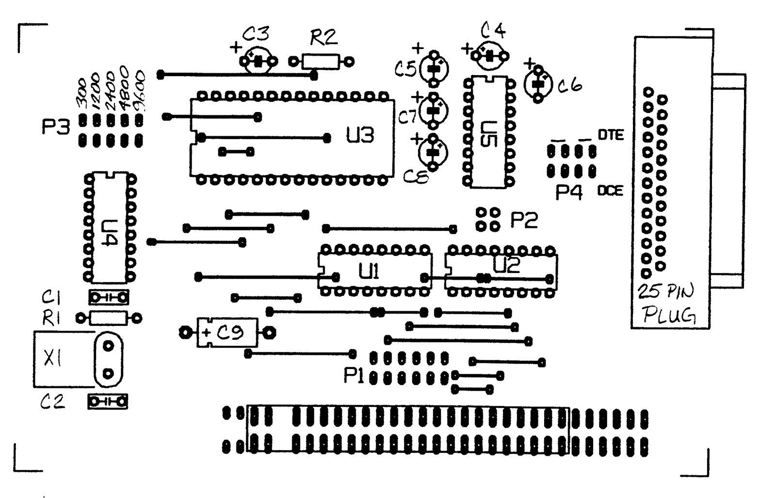
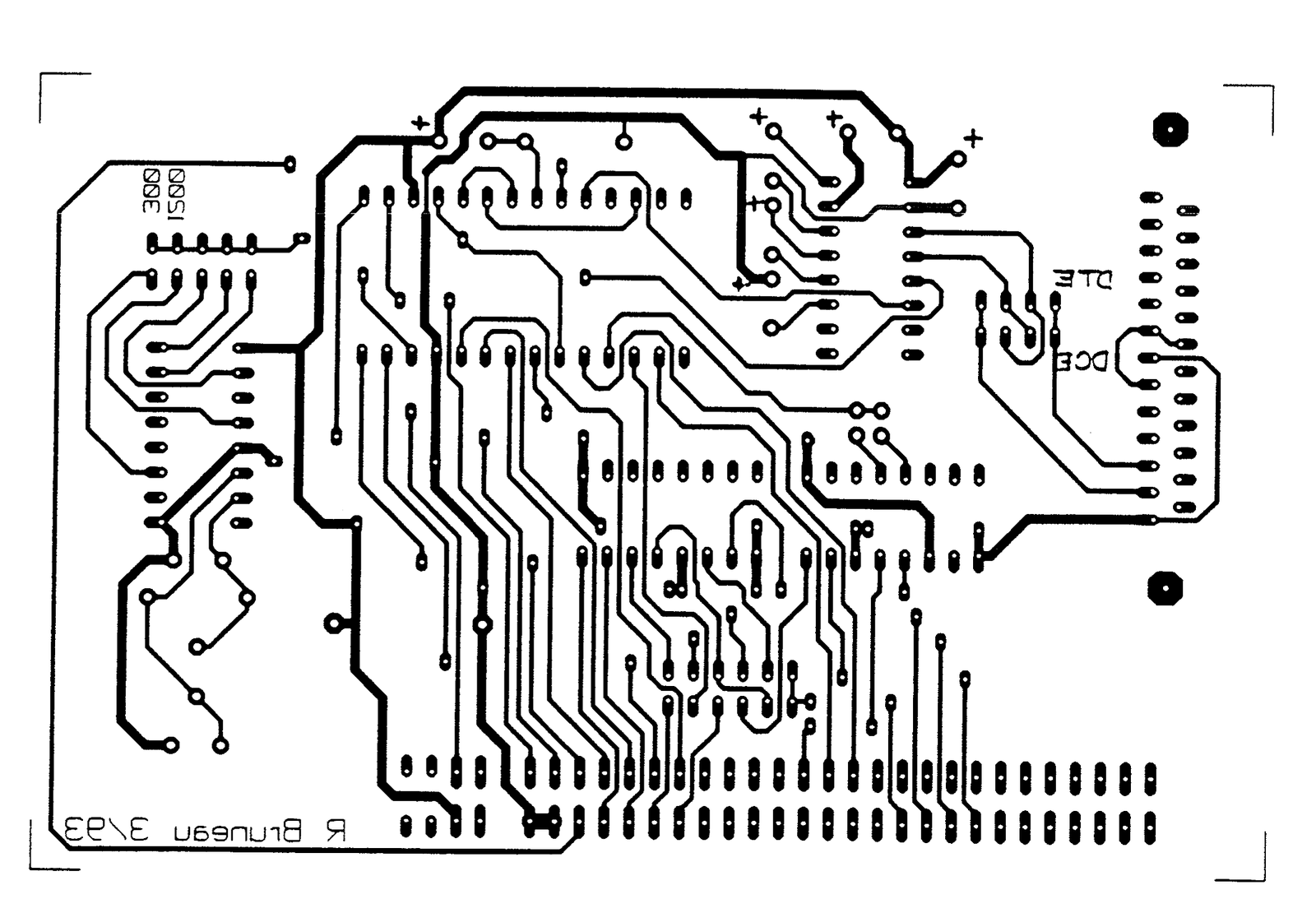
As with all the projects I have presented in the past, the artwork is meant to be photocopied onto TEC-200 mylar or equivalent and transferred to a clean circuit board. There are 2[illegible] wire jumpers on the board and these should be installed before the sockets. Most of the capacitors are electrolytic and can only be installed one way – match the + sign. Install the crystal on it’s side as shown on the component overlay using a piece of double-sided tape to anchor it in place.
There are four areas on the board:
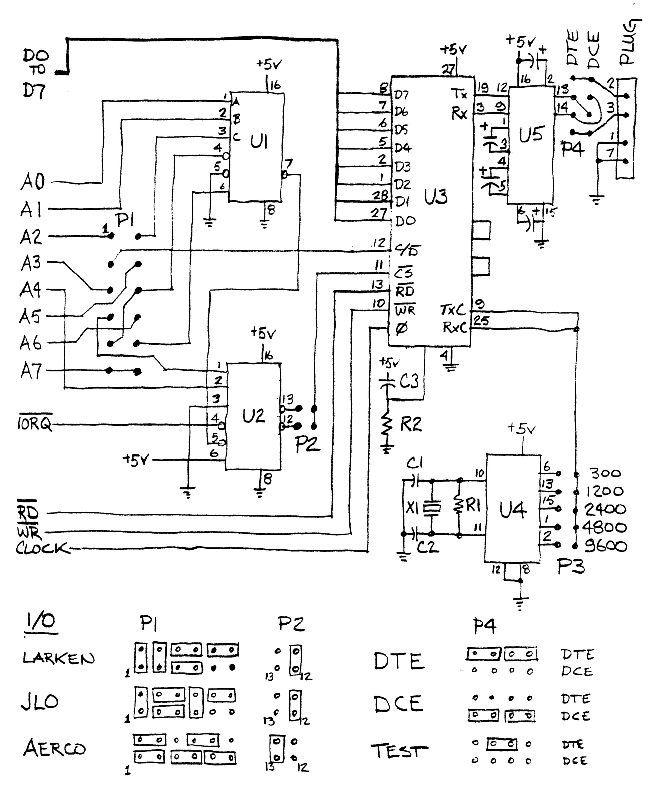
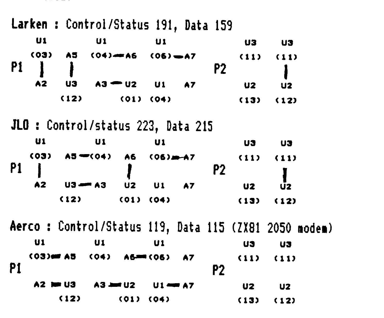
I/O mapping (P1, P2) – Larken, JLO, Aerco
Baud Rate (P3) – 300, 1200, 2400, 4800, 9600
DTE/DCE Configuration (P4) – null modem
Use wire jumpers for permanent configuration, or pin strips and shorting blocks (recommended for P3) to allow you to change the settings when ever you want. For the 2068 this board can be adapted to suit the Larken, JLO, and Aerco systems by moving shorting blocks as shown below. For the ZX81, use the Aerco setup which matches the 2050 modem port addresses.
One shorting block is used on P3 to select the baud rate starting from the left: 300, 1200, 2400, 4800.
The purpose for P4 is to switch the transmit and receive pins on the subd25 plug to match the device that you will connect to. To communicate with another computer, use two shorting blocks on P4 to make a DTE null modem connection, eliminating the need to convert or purchase a null modem.
Before you install any of the chips, plug the board on the back of your computer, turn it on and confirm that the system runs. Check that +5v appears at pins 16 on U1,U2,U4 and U6, and at pin 26 of U3. If everything checks out, you can proceed with loading the chips.
TESTING
At this time we are presupposing that you have access to one of the communication packages available for your computer, MAXCOM or ZXTERM-80 for example. For both the ZX81 and 2068 no changes to the software are required. With P3 set to 1200, the 8251 will divide the clock by 64 to give 300 baud for the ZX81. For the 2068, the 8251 will divide the clock by 16 or 64 to give 300 or 1200 baud depending on your selection of UART setup. Connect a temporary jumper between pins 2 (transmit) and 3 (receive) of the Subd25 socket. Load your software, go to terminal mode, and punch some keys. If everything is working you should see characters print to the screen as you key them in. If nothing happens, there may be a problem with the baud rate or mapping. Make sure that you have shorted the correct pins. If the board appears to work, remove the jumper and connect it to another computer with the Null-Modem settings and continue your testing.
Articles covering computer-computer data transfers were presented in past issues of this newsletter. Discussions with Larry Kenny indicate that MAXCOM can be upgraded to faster baud rates if the print-to-screen routine is disabled during transfers – we are investigating. For the ZX81, Vince Lee, of VSUG, wrote several articles in ZX-APPEAL using an adapted 2050 modem/serial board and his routines should work with this board.
Anyone who requires more information or would like to correspond regarding this article or past ones can contact me in writing through the club.
REFERENCES
- Z-SI/O RS-232C Serial Interface Card …… Clifford & Associates
- An 8031 In-circuit Emulator, George DinWiddie, BYTE Magazine, July 1986
- The ZX/TS Serial Link, V. Lee, ZX-Appeal, Summer 1990
COMPONENT LIST
U1              74LS138      DIL-16
U2              74LS138      DIL-16
U3              8251         DIL-28
U4              74HC4060     DIL-16
U5              MAX232       DIL-16
R1              15m          1/4-watt
R2              1k           1/4-watt
C1,C2           20pF         Ceramic
C3              2.2uF/16v    Tantalum
C4,C5,C6,C7,C8  22uF/16v     Electrolytic
C9              10uF/16v     Electrolytic
X1              9.8403Mh     Crystal HC18
P1              I/O-a        SIL-2X06 (2 rows of 6 pins)
P2              I/O-b        SIL-2X02 (2 rows of 2 pins)
P3              BAUD         SIL-2X05 (2 rows of 5 pins)
P4              DTE/DCE      SIL-2X04 (2 rows of 4 pins)
P1              PLUG         SUBD25 (male)

Miscellaneous:  Edge connector and extender, fine copper
                wire, 16 pin sockets, 28 pin socket