This project was found in the November and December 1986 issues of SINCLAIR USER and is suitable for both the 2068 and the ZX81. The original article was written by Rupert Goodwins and his design was based on a simple platform with two powered wheels and a caster. You could easily substitute a cheap plastic motorized toy (one that is powered by an attached cable and handset). Here one motor drives the rear wheels and the other motor turns the front tires.
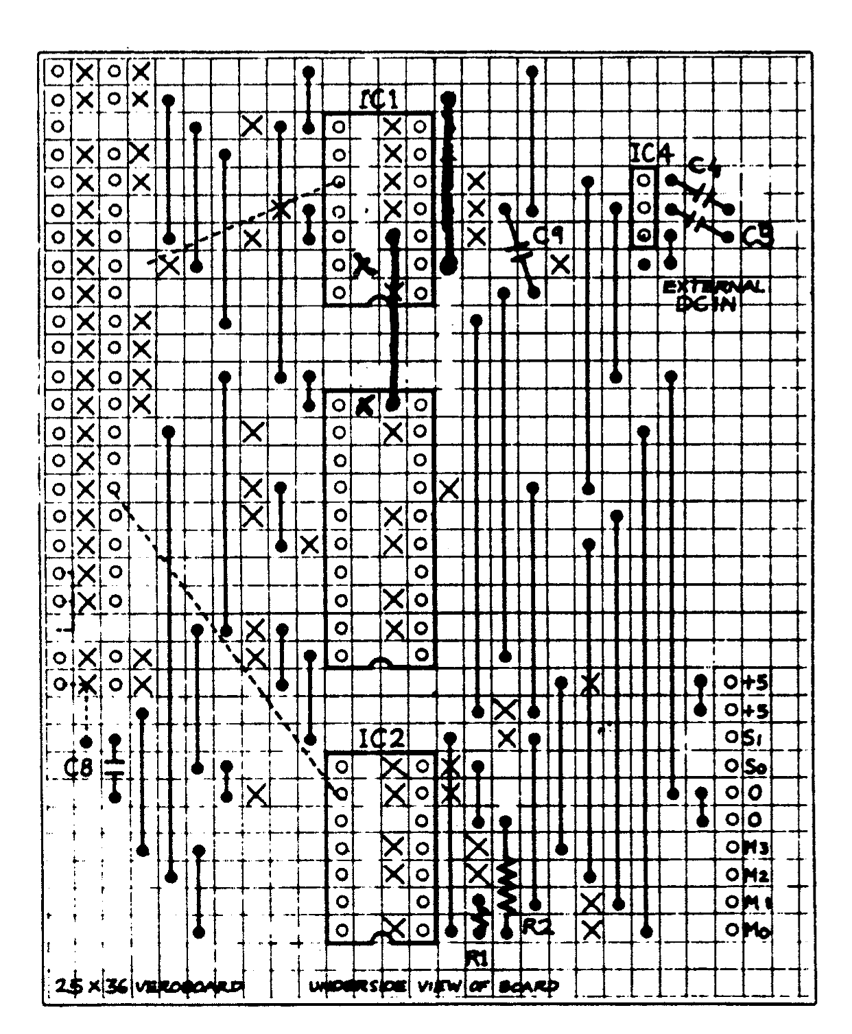
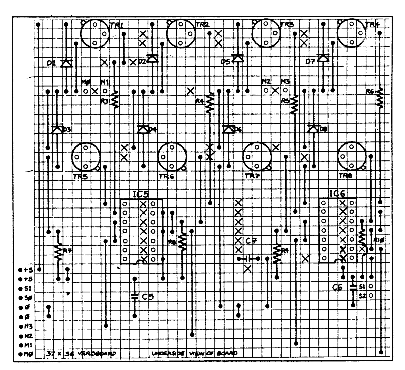
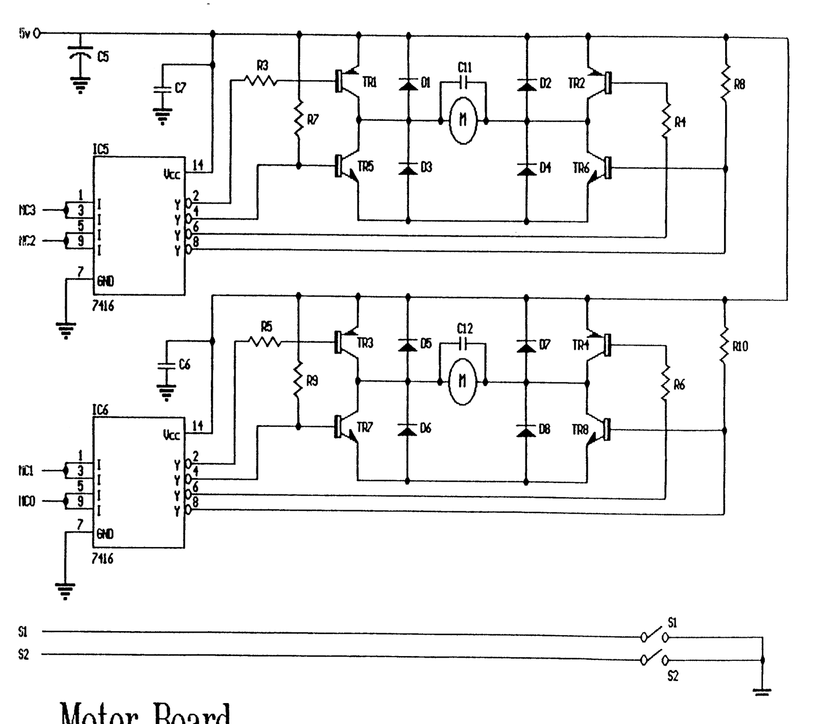
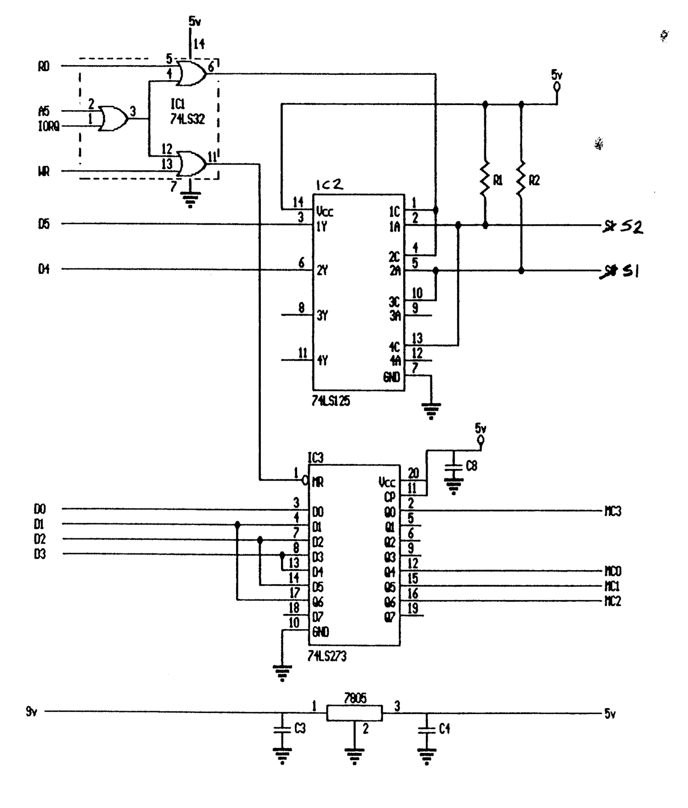
The project consists of two circuits built up on VEROboard. The first circuit and board layout is for a simple Input/Output board that plugs into the back of the computer. If you already have an I/O board, you don’t need to construct this interface. The second circuit and board layout is for a Motor board which provides the switching logic to control the direction that the motors will turn (the layouts are done on graph paper that has the same pitch as the holes in the VEROboard). A ribbon cable between the interface and motor board carries the control signals and power to the motors. Note that the interface and motor boards will not control the speed of the motors, just the direction.
Construction is started by cutting the VEROboard to size (25 x 36 holes and 37 x 36 holes). IMPORTANT NOTE: the board layouts show the bottom or copper side of the VEROboard. That means that the transistors and ICs are being viewed from the bottom! Locate and cut the traces marked by an x on the layouts. A permanent marker makes the job easier to catch mistakes before you cut. Insert all of the jumpers before you load the components, again making sure that you have the right holes. Use sockets for the ICs and be careful not to overheat the diodes and transistors when you solder them in. Check both boards for shorts or misplaced bits.
Before you insert the ICs, plug in the interface board and turn the computer on. If the computer does not come up, power off and check for shorts or misrouting on the lines and leads coming from the edge connector. If everything is ok, insert the ICs and test again.
Connect the two boards together with the ribbon cable, hook up the switches but not the motors, and try the following tests:
2068
10 PRINT IN 31;" ";:INPUT " ":GOTO 10ZX81
1 REM XXXXXXXXXXXXXXXXX
10 FOR X=16514 TO 16519
20 INPUT A
30 POKE X,A
40 NEXT X
100 PRINT USR 16514;" ";
110 GOTO 100
Input the following machine code ignoring the information after the semicolon:
219 31          ;IN A,(31)
79              ;LD C,A
6   0           ;LD B,0
201             ;RET
You should get a screenfull of 255’s, which change to 223’s, 239’s and 207’s as the switches are pressed. If you don’t get 255’s then check the wiring around IC1 and IC2 on the interface board. Next, switch everything off and connect the motors. Switch on again. If one or other of the motors starts, try switching on again. If the condition persists, check the wiring around IC3, the area around the transistors and the diodes. If the motors are silent, then try the following tests:
2068
OUT 31,1        one motor should start
OUT 31,2        same motor should reverse
OUT 31,0        stops motor

OUT 31,4        the other motor should start
OUT 31,8        reverse
OUT 31,0        stop
To get both motors running, add the numbers together:
OUT 31,5        Both motors running
OUT 31,9        1st motor forward, 2nd motor reverse
OUT 31,10       both motors reverse
OUT 31,6        1st motor reverse, 2nd motor forward
ZX81
1 REM XXXXXXXXXXX
10 FOR X=16520 TO 16524
20 INPUT A
30 POKE X,A
40 NEXT X
100 PRINT "INPUT CONTROL NUMBER: 1,2, 4,8, 5,9,10,6, 0"
110 INPUT X
120 POKE 16521,X
110 RAND USR 16520
110 GOTO 100
Input the following machine code ignoring the information after the semicolon:
62  0           ;LD A,0
211 31          ;OUT 31,A
201             ;RET
The results should be the same as for the 2068.
COMPONENTS:
Interface Board                          Motor Board

IC1     74LS32                           IC5,6   7416
IC2     74LS125                          TR1-4   PNP, TIP36 or equivalent
IC3     74LS273                          TR5-8   NPN, TIP35 or equivalent
IC4     7805                             D1-8    1N4001
R1,2    10K                              R3-10   150 ohms
C3,4,8  100nF                            C5      1000uF 25v Electrolytic
MISC    VEROboard 25 x 26 holes          C6,7    100nF
        Wirewrap edge connector with     MISC    VEROboard 37 x 36 holes
              polarizing key at position 3       2 SPST Switches, Normally Open
        Small heat sink for 7805                 6 ft 10 wire Ribbon Cable
                                                 2 5v Geared Motors with wheels