
January 1993
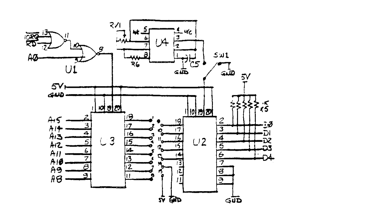
Some time ago, I came across an article in SYNC that provided the ZX81 with a hardware key-repeat feature. Under normal conditions, the ZX81 operating system requires you to press and release each key before it will process the next key pressed. This is done in the key scan routine where the code checks to see if the key pressed is the same as before or if it is different. If there is a change, the new key value is accepted and processed. The repeat-key circuit uses a timer chip to toggle a buffer on and off at a slower rate than the key scan. Each time the buffer is off, the key scan detects a ‘no key pressed’ condition and accepts the pressed key value each time the buffer is on. The function can be disabled with a switch.
The keyboard buffer circuit is based on an article in a back issue of ‘YOUR SINCLAIR’. With the omission of the timer chip and associated components (marked with an asterix in the component list and boxed on the circuit diagram) the buffer will work on a 2068. The cable between the keyboard and the computer can be several feet long.
THE HARDWARE
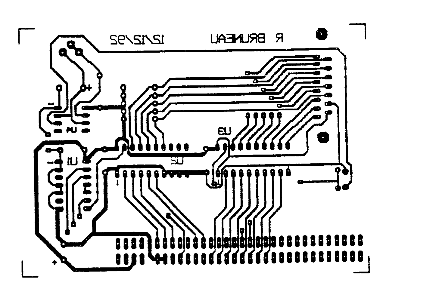
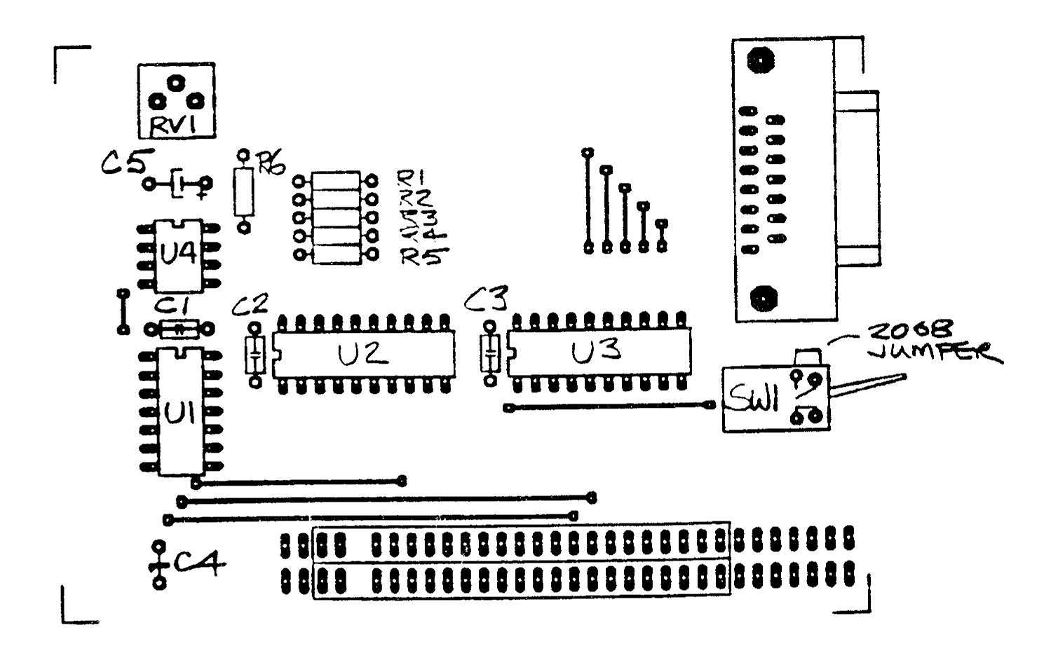
A PCB mask has been provided for photocopying onto TEC 200 mylar film to be transferred to a blank circuit board. Load the components as shown on the overlay, being careful to install the sockets and capacitors correctly. The edge connector is located on the component side of the board, with the extender on the side facing away from the computer. Omit the marked components if the buffer is intended for a 2068 and solder a jumper across the switch pads as noted. Check for poor solder joints and jumps between traces and clean any that are suspect. Before you install the ICs on the board, plug the assembly onto the rear edge connector of your computer, turn it on, and confirm that the computer initializes properly. If it doesn’t, quickly shut off the machine and check your work again.
TESTING
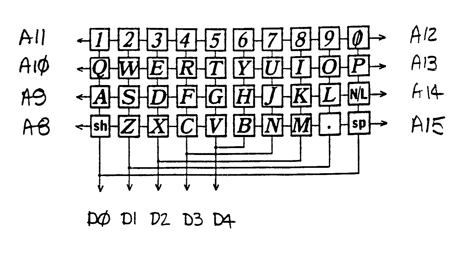
Set the trim pot to the centre of its adjustment. Use a bare wire to short one of the A8 – A15 lines to one of the KBD lines. A character should appear on the screen and repeat until you remove the wire. Adjust the trim pot to achieve the desired repeat rate. If the rate is too high, no characters will print. To fully test the board, you have to construct or adapt a keyboard to connect to the buffer board. A suggested layout is shown, copied from Mike Lord‘s “THE EXPLORER’S GUILD TO THE ZX81 AND TIMEX SINCLAIR 1000“.
COMPONENT LIST
U1   74LS32
U2   74LS245
U3   74LS245
U4   *LM555 timer
C1   100nF polyester
C2   100nF polyester
C3   100nF polyester
C4   4.7uF - 10v tantalum
C5   *100uF - 10v electolytic
R1   1K - 1/4 watt resister
R2   1K - 1/4 watt resister
R3   1K - 1/4 watt resister
R4   1K - 1/4 watt resister
R5   1K - 1/4 watt resister
R6   *1K - 1/4 watt resister
RV1  *10K vertical trimpot
S1   *SPDT toggle or slide switch
J1   SUBD15 female connector
J2   SUBD15 male connector
J3   ZX81 or 2068 Edge connector

*    Used for ZX81 Key Repeat