
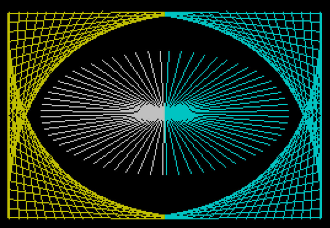
MIRROR is a graphics program that draws a symmetrical pattern by plotting diagonal lines and an elliptical arc, then mirrors the left half of the screen to the right half using POINT and PLOT. The first drawing loop (lines 20–50) creates a series of lines from the left edge using STEP 7.55 to produce a fan-like or geometric fill effect. Lines 60–80 add an arc drawn from a fixed point using trigonometric functions with COS and SIN, producing an ellipse segment. The pixel-level mirror in lines 9990–9992 reads each lit pixel in the left 128 columns and replicates it symmetrically in the right 128 columns. A second mirror pass (lines 9993–9999) operates directly on the Spectrum’s display file at address 22528, copying attribute or pixel rows using PEEK and POKE to mirror 16-byte blocks within each character row, effectively reflecting the left half of the screen data at the memory level.
Program Structure
The program is divided into four functional phases:
- Setup (line 15): Sets BORDER, PAPER, and INK attributes and clears the screen.
- Geometric line drawing (lines 20–50): Draws a fan of diagonal lines from the left edge using a
FORloop with a non-integer STEP of 7.55. - Arc drawing (lines 60–80): Draws an elliptical arc using trigonometric functions from a fixed origin point.
- Mirroring (lines 9990–9999): Two separate mirroring passes — one pixel-level via
POINT/PLOT, and one memory-level viaPEEK/POKEon the display file.
Drawing Phase — Lines 20–50
The loop variable I runs from 1 to 168 in steps of 7.55, giving approximately 22 iterations. Each iteration plots two lines:
PLOT 0,(168-I): DRAW I,-(168-I)— draws a line from the left edge downward toward the bottom-right.PLOT 0,I: DRAW I,-I+168— draws a complementary line creating a reflected fan effect about the horizontal midpoint.
Using a fractional STEP of 7.55 rather than an integer produces uneven spacing that gives the fan a slightly irregular, organic appearance.
Arc Drawing — Lines 60–80
The arc is drawn in INK 7 (white) from pixel coordinate (127, 86), using parametric equations: DRAW 100*COS I, 50*SIN I with I stepping from 1.6 to 4.7 in steps of 0.1. This traces a partial ellipse with a horizontal radius of 100 pixels and a vertical radius of 50 pixels. After the arc, INK is set to 5 (cyan) for subsequent operations.
Pixel Mirror Pass — Lines 9990–9992
This pass iterates over all 176 pixel rows and the left 128 columns (0–127). For each pixel found to be set (POINT (I,J)=1), it plots the mirror image at column 255-I on the same row. This is a straightforward but slow approach since POINT and PLOT are called for every candidate pixel, resulting in up to 22,528 individual checks. The high line numbers (9990–9992) suggest this section was added or modified separately from the main drawing code.
Memory-Level Mirror Pass — Lines 9993–9999
The second mirror operates directly on the Spectrum display file starting at address 22528 (L), with a destination offset of 16 bytes into each row (G = L + 16). For each of the 22 character rows, it reads bytes at offsets 15 down to 0 from L and writes them in reverse order starting at G. Both L and G advance by 32 bytes per row iteration.
This byte-reversal mirrors the 16 left-hand bytes of each character row into the 16 right-hand bytes, but it does so at the character-row level rather than the pixel-scan-line level. On the Spectrum, display memory is organized in a non-linear fashion (bank/row/column), so this operation will not produce a clean pixel mirror for all rows — it mirrors character rows correctly only for scan line 0 of each character row, producing artifacts on scan lines 1–7.
Notable Techniques
- Using
POINTto read pixel state for a software mirror is a well-known but slow BASIC technique; a pure PEEK-based approach would be significantly faster. - The memory mirror in lines 9993–9999 attempts to speed up the operation by working directly with display RAM, but the Spectrum’s non-linear screen layout means
L=L+32only advances one scan line, not one full character row (which would require stepping through 8 scan lines). - Parametric ellipse drawing via
DRAWwithCOS/SINis an efficient idiom for curves in Spectrum BASIC, asDRAWaccumulates relative coordinates from the last plot point. - The separation of line numbers into a low block (10–80) and a high block (9990–9999) is a common technique to reserve space for additions to the main program without renumbering.
Potential Bugs and Anomalies
- The memory mirror (lines 9993–9999) initializes
G=22544, which isL+16, targeting bytes 16–31 of the first display row. This correctly positions the right half of the first character row. However, advancing bothLandGby 32 bytes steps through individual scan lines rather than full character rows, which is actually correct for a linear traversal — but the outer loop runs only 22 times (one per character row), not 176 times (one per scan line), so only the first scan line of each character row is processed. This is a bug that will leave scan lines 1–7 of each character row un-mirrored at the memory level. - The pixel mirror at line 9991 uses
POINT (I,J)=1, which only detects INK pixels. Pixels that were plotted in INK 0 against a non-zero PAPER color would be missed, though in this program PAPER is 0 throughout.
Image Gallery
Source Code
   10 REM MIRROR
   15 BORDER 0: PAPER 0: INK 6: CLS
   20 FOR I=1 TO 168 STEP 7.55
   30 PLOT 0,(168-I): DRAW I,-(168-I)
   40 PLOT 0,I: DRAW I,-I+168
   50 NEXT I
   60 FOR I=1.6 TO 4.7 STEP .1
   70 INK 7: PLOT 127,86: DRAW 100*COS I,50*SIN I
   80 NEXT I: INK 5
 9990 FOR J=0 TO 175: FOR I=0 TO 127
 9991 IF POINT (I,J)=1 THEN PLOT 255-I,J
 9992 NEXT I: NEXT J
 9993 LET L=22528: LET G=22544
 9994 FOR J=1 TO 22
 9995 FOR I=15 TO 0 STEP -1
 9996 POKE g+(15-I),PEEK (L+I)
 9997 NEXT I
 9998 LET L=L+32: LET G=G+32
 9999 NEXT J
Note: Type-in program listings on this website use ZMAKEBAS notation for graphics characters.