This program stores two machine code routines in REM statements for cassette tape I/O on a ZX81/TS1000, invoked via RAND USR 16514 (write) and RAND USR 16549 (read). The Z80 machine code at line 10 implements low-level tape routines that bypass the built-in SAVE/LOAD, likely for faster or custom data transfer. The routines reference address 16400 (0x4010) to locate an array and use IN/OUT instructions (DB FE / D3 FF) for direct ULA port access during tape operations. A DIM statement must be executed first to allocate the array space that the machine code accesses. Line 50 saves the program to tape under the name “10075”.
Program Analysis
Program Structure
The program is minimal by design — it exists primarily as a carrier for embedded machine code. Its six lines serve distinct roles:
- Line 10 — REM statement containing the raw Z80 machine code for both tape routines.
- Line 20 — REM comment documenting that a DIM statement must be run first to allocate array space.
- Line 30 — REM documenting the entry point address for the write routine: RAND USR 16514.
- Line 40 — REM documenting the entry point address for the read routine: RAND USR 16549.
- Line 50 — SAVE command to store the program to tape.
- Line 60 — LIST to display the program after loading.
The two entry point addresses (16514 and 16549) are offsets into line 10’s REM data. On a ZX81/TS1000, a REM statement’s byte content begins at a fixed offset after the line header, placing the machine code at predictable absolute addresses as long as this line is first in the program — hence the explicit note in line 20.
Machine Code Disassembly
The REM at line 10 contains 69 bytes of Z80 code. The two routines share the same REM block, with the write routine starting at offset 0 and the read routine following it. Key instructions identified:
CD E7 02— CALL 02E7h, invoking a ZX81 ROM routine (likely the display/sync routine).2A 10 40— LD HL,(4010h), loading the address stored at 16400 — the start of the user array allocated by DIM.23 4E 23 46 23— INC HL; LD C,(HL); INC HL; LD B,(HL); INC HL — reading a 16-bit length value from the array header into BC.DB FE— IN A,(FEh), reading from the ULA/tape-in port.D3 FF— OUT (FFh),A, writing to the tape-out port.17— RLA, rotating the tape bit into the carry flag for serial decoding.CB 16— RL (HL), rotating carry into the byte being assembled from tape.C9— RET, returning to BASIC.
Tape I/O Technique
Both routines use direct port I/O rather than the ROM’s built-in SAVE/LOAD. Port FEh is the standard ZX81 ULA input port (bit 7 carries the tape signal), and port FFh is used for tape output. The read routine uses RLA to shift successive tape bits into the carry flag, then RL (HL) to build bytes one bit at a time, with loop counters managing bit depth (0E 08 loads C with 8 for the bit loop) and byte count from the array length field in BC.
The write routine similarly loops over the array data, outputting each bit via OUT (FFh),A. The check FE 56 / 30 E4 (CP 56h; JR NC) appears to be a timing or sync-byte threshold test during the read loop.
Array Addressing Convention
Both routines locate data via LD HL,(4010h). Address 4010h (16400 decimal) is the ZX81/TS1000 system variable E_LINE area or more precisely a pointer the author has arranged to hold the array’s base address. The subsequent three INC HL / LD r,(HL) instructions walk past the array’s type byte to read its 16-bit length into BC, which then drives the byte-count loop. This requires the DIM statement to have been executed beforehand, as stated in line 20.
Entry Point Arithmetic
On a ZX81/TS1000, when this program is first in memory, line 10 begins at address 16509 (407Dh). The REM token and length bytes occupy 5 bytes of header, placing the first machine code byte at 16514 — exactly the write entry point stated in line 30. The read routine begins 35 bytes later at 16549, matching line 40’s documentation.
Notable Techniques and Observations
- Storing machine code in a REM is the standard ZX81 technique; the mandatory “first in program” constraint preserves the absolute addresses.
- The DJNZ / DJNZ pattern (
10 F6,10 F5) provides tight inner timing loops critical for reliable tape speed. 3F(CCF — complement carry flag) appears in the read path, used to invert the tape bit polarity between phases.- The
C5/C1(PUSH BC / POP BC) instructions preserve the byte counter across the inner bit loop. 78 B1(LD A,B; OR C) followed byC8(RET Z) or20 F4(JR NZ) implements a 16-bit zero-test on BC for the outer loop termination, a common Z80 idiom.
Content
Image Gallery
Source Code
10 REM \CD\E7
Skip to content
Tape Read/Write Routines
This file is part of and Timex Sinclair Public Domain Library Tape 1002. Download the collection to get this file.
This program stores two machine code routines in REM statements for cassette tape I/O on a ZX81/TS1000, invoked via RAND USR 16514 (write) and RAND USR 16549 (read). The Z80 machine code at line 10 implements low-level tape routines that bypass the built-in SAVE/LOAD, likely for faster or custom data transfer. The routines reference address 16400 (0x4010) to locate an array and use IN/OUT instructions (DB FE / D3 FF) for direct ULA port access during tape operations. A DIM statement must be executed first to allocate the array space that the machine code accesses. Line 50 saves the program to tape under the name “10075”.
Program Analysis
Program Structure
The program is minimal by design — it exists primarily as a carrier for embedded machine code. Its six lines serve distinct roles:
- Line 10 — REM statement containing the raw Z80 machine code for both tape routines.
- Line 20 — REM comment documenting that a DIM statement must be run first to allocate array space.
- Line 30 — REM documenting the entry point address for the write routine: RAND USR 16514.
- Line 40 — REM documenting the entry point address for the read routine: RAND USR 16549.
- Line 50 — SAVE command to store the program to tape.
- Line 60 — LIST to display the program after loading.
The two entry point addresses (16514 and 16549) are offsets into line 10’s REM data. On a ZX81/TS1000, a REM statement’s byte content begins at a fixed offset after the line header, placing the machine code at predictable absolute addresses as long as this line is first in the program — hence the explicit note in line 20.
Machine Code Disassembly
The REM at line 10 contains 69 bytes of Z80 code. The two routines share the same REM block, with the write routine starting at offset 0 and the read routine following it. Key instructions identified:
CD E7 02 — CALL 02E7h, invoking a ZX81 ROM routine (likely the display/sync routine).2A 10 40 — LD HL,(4010h), loading the address stored at 16400 — the start of the user array allocated by DIM.23 4E 23 46 23 — INC HL; LD C,(HL); INC HL; LD B,(HL); INC HL — reading a 16-bit length value from the array header into BC.DB FE — IN A,(FEh), reading from the ULA/tape-in port.D3 FF — OUT (FFh),A, writing to the tape-out port.17 — RLA, rotating the tape bit into the carry flag for serial decoding.CB 16 — RL (HL), rotating carry into the byte being assembled from tape.C9 — RET, returning to BASIC.
Tape I/O Technique
Both routines use direct port I/O rather than the ROM’s built-in SAVE/LOAD. Port FEh is the standard ZX81 ULA input port (bit 7 carries the tape signal), and port FFh is used for tape output. The read routine uses RLA to shift successive tape bits into the carry flag, then RL (HL) to build bytes one bit at a time, with loop counters managing bit depth (0E 08 loads C with 8 for the bit loop) and byte count from the array length field in BC.
The write routine similarly loops over the array data, outputting each bit via OUT (FFh),A. The check FE 56 / 30 E4 (CP 56h; JR NC) appears to be a timing or sync-byte threshold test during the read loop.
Array Addressing Convention
Both routines locate data via LD HL,(4010h). Address 4010h (16400 decimal) is the ZX81/TS1000 system variable E_LINE area or more precisely a pointer the author has arranged to hold the array’s base address. The subsequent three INC HL / LD r,(HL) instructions walk past the array’s type byte to read its 16-bit length into BC, which then drives the byte-count loop. This requires the DIM statement to have been executed beforehand, as stated in line 20.
Entry Point Arithmetic
On a ZX81/TS1000, when this program is first in memory, line 10 begins at address 16509 (407Dh). The REM token and length bytes occupy 5 bytes of header, placing the first machine code byte at 16514 — exactly the write entry point stated in line 30. The read routine begins 35 bytes later at 16549, matching line 40’s documentation.
Notable Techniques and Observations
- Storing machine code in a REM is the standard ZX81 technique; the mandatory “first in program” constraint preserves the absolute addresses.
- The DJNZ / DJNZ pattern (
10 F6, 10 F5) provides tight inner timing loops critical for reliable tape speed.
3F (CCF — complement carry flag) appears in the read path, used to invert the tape bit polarity between phases.- The
C5 / C1 (PUSH BC / POP BC) instructions preserve the byte counter across the inner bit loop.
78 B1 (LD A,B; OR C) followed by C8 (RET Z) or 20 F4 (JR NZ) implements a 16-bit zero-test on BC for the outer loop termination, a common Z80 idiom.
Content
Image Gallery

Source Code
10 REM \CD\E7\02\06\0E\21\00\FF\2B\7C\B5\20\FB\10\F6\2A\10\40\23\4E\23\46\23\C5\5E\CD\1F\03\C1\0B\78\B1\20\F4\C9\CD\E7\02\2A\10\40\23\4E\23\46\23\C5\1E\08\DB\FE\D3\FF\17\30\F9\0E\94\06\1A\0D\DB\FE\17\CB\79\79\38\F5\10\F5\20\04\FE\56\30\E4\3F\CB\16\1D\20\DE\C1\0B\78\B1\C8\18\D3
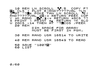
20 REM DIM SPACE FOR ARRAY MUST BE FIRST IN PGM.
30 REM RAND USR 16514 TO WRITE
40 REM RAND USR 16549 TO READ
50 SAVE "1007%5"
60 LIST
Note: Type-in program listings on this website use ZMAKEBAS notation for graphics characters.
People
No people associated with this content.
Skip to content
Tape Read/Write Routines
This file is part of and Timex Sinclair Public Domain Library Tape 1002. Download the collection to get this file.
This program stores two machine code routines in REM statements for cassette tape I/O on a ZX81/TS1000, invoked via RAND USR 16514 (write) and RAND USR 16549 (read). The Z80 machine code at line 10 implements low-level tape routines that bypass the built-in SAVE/LOAD, likely for faster or custom data transfer. The routines reference address 16400 (0x4010) to locate an array and use IN/OUT instructions (DB FE / D3 FF) for direct ULA port access during tape operations. A DIM statement must be executed first to allocate the array space that the machine code accesses. Line 50 saves the program to tape under the name “10075”.
Program Analysis
Program Structure
The program is minimal by design — it exists primarily as a carrier for embedded machine code. Its six lines serve distinct roles:
- Line 10 — REM statement containing the raw Z80 machine code for both tape routines.
- Line 20 — REM comment documenting that a DIM statement must be run first to allocate array space.
- Line 30 — REM documenting the entry point address for the write routine: RAND USR 16514.
- Line 40 — REM documenting the entry point address for the read routine: RAND USR 16549.
- Line 50 — SAVE command to store the program to tape.
- Line 60 — LIST to display the program after loading.
The two entry point addresses (16514 and 16549) are offsets into line 10’s REM data. On a ZX81/TS1000, a REM statement’s byte content begins at a fixed offset after the line header, placing the machine code at predictable absolute addresses as long as this line is first in the program — hence the explicit note in line 20.
Machine Code Disassembly
The REM at line 10 contains 69 bytes of Z80 code. The two routines share the same REM block, with the write routine starting at offset 0 and the read routine following it. Key instructions identified:
CD E7 02 — CALL 02E7h, invoking a ZX81 ROM routine (likely the display/sync routine).2A 10 40 — LD HL,(4010h), loading the address stored at 16400 — the start of the user array allocated by DIM.23 4E 23 46 23 — INC HL; LD C,(HL); INC HL; LD B,(HL); INC HL — reading a 16-bit length value from the array header into BC.DB FE — IN A,(FEh), reading from the ULA/tape-in port.D3 FF — OUT (FFh),A, writing to the tape-out port.17 — RLA, rotating the tape bit into the carry flag for serial decoding.CB 16 — RL (HL), rotating carry into the byte being assembled from tape.C9 — RET, returning to BASIC.
Tape I/O Technique
Both routines use direct port I/O rather than the ROM’s built-in SAVE/LOAD. Port FEh is the standard ZX81 ULA input port (bit 7 carries the tape signal), and port FFh is used for tape output. The read routine uses RLA to shift successive tape bits into the carry flag, then RL (HL) to build bytes one bit at a time, with loop counters managing bit depth (0E 08 loads C with 8 for the bit loop) and byte count from the array length field in BC.
The write routine similarly loops over the array data, outputting each bit via OUT (FFh),A. The check FE 56 / 30 E4 (CP 56h; JR NC) appears to be a timing or sync-byte threshold test during the read loop.
Array Addressing Convention
Both routines locate data via LD HL,(4010h). Address 4010h (16400 decimal) is the ZX81/TS1000 system variable E_LINE area or more precisely a pointer the author has arranged to hold the array’s base address. The subsequent three INC HL / LD r,(HL) instructions walk past the array’s type byte to read its 16-bit length into BC, which then drives the byte-count loop. This requires the DIM statement to have been executed beforehand, as stated in line 20.
Entry Point Arithmetic
On a ZX81/TS1000, when this program is first in memory, line 10 begins at address 16509 (407Dh). The REM token and length bytes occupy 5 bytes of header, placing the first machine code byte at 16514 — exactly the write entry point stated in line 30. The read routine begins 35 bytes later at 16549, matching line 40’s documentation.
Notable Techniques and Observations
- Storing machine code in a REM is the standard ZX81 technique; the mandatory “first in program” constraint preserves the absolute addresses.
- The DJNZ / DJNZ pattern (
10 F6, 10 F5) provides tight inner timing loops critical for reliable tape speed.
3F (CCF — complement carry flag) appears in the read path, used to invert the tape bit polarity between phases.- The
C5 / C1 (PUSH BC / POP BC) instructions preserve the byte counter across the inner bit loop.
78 B1 (LD A,B; OR C) followed by C8 (RET Z) or 20 F4 (JR NZ) implements a 16-bit zero-test on BC for the outer loop termination, a common Z80 idiom.
Content
Image Gallery
Source Code
10 REM \CD\E7\02\06\0E\21\00\FF\2B\7C\B5\20\FB\10\F6\2A\10\40\23\4E\23\46\23\C5\5E\CD\1F\03\C1\0B\78\B1\20\F4\C9\CD\E7\02\2A\10\40\23\4E\23\46\23\C5\1E\08\DB\FE\D3\FF\17\30\F9\0E\94\06\1A\0D\DB\FE\17\CB\79\79\38\F5\10\F5\20\04\FE\56\30\E4\3F\CB\16\1D\20\DE\C1\0B\78\B1\C8\18\D3
20 REM DIM SPACE FOR ARRAY MUST BE FIRST IN PGM.
30 REM RAND USR 16514 TO WRITE
40 REM RAND USR 16549 TO READ
50 SAVE "1007%5"
60 LIST
Note: Type-in program listings on this website use ZMAKEBAS notation for graphics characters.
People
No people associated with this content.
E
Skip to content
Tape Read/Write Routines
This file is part of and Timex Sinclair Public Domain Library Tape 1002. Download the collection to get this file.
This program stores two machine code routines in REM statements for cassette tape I/O on a ZX81/TS1000, invoked via RAND USR 16514 (write) and RAND USR 16549 (read). The Z80 machine code at line 10 implements low-level tape routines that bypass the built-in SAVE/LOAD, likely for faster or custom data transfer. The routines reference address 16400 (0x4010) to locate an array and use IN/OUT instructions (DB FE / D3 FF) for direct ULA port access during tape operations. A DIM statement must be executed first to allocate the array space that the machine code accesses. Line 50 saves the program to tape under the name “10075”.
Program Analysis
Program Structure
The program is minimal by design — it exists primarily as a carrier for embedded machine code. Its six lines serve distinct roles:
- Line 10 — REM statement containing the raw Z80 machine code for both tape routines.
- Line 20 — REM comment documenting that a DIM statement must be run first to allocate array space.
- Line 30 — REM documenting the entry point address for the write routine: RAND USR 16514.
- Line 40 — REM documenting the entry point address for the read routine: RAND USR 16549.
- Line 50 — SAVE command to store the program to tape.
- Line 60 — LIST to display the program after loading.
The two entry point addresses (16514 and 16549) are offsets into line 10’s REM data. On a ZX81/TS1000, a REM statement’s byte content begins at a fixed offset after the line header, placing the machine code at predictable absolute addresses as long as this line is first in the program — hence the explicit note in line 20.
Machine Code Disassembly
The REM at line 10 contains 69 bytes of Z80 code. The two routines share the same REM block, with the write routine starting at offset 0 and the read routine following it. Key instructions identified:
CD E7 02 — CALL 02E7h, invoking a ZX81 ROM routine (likely the display/sync routine).2A 10 40 — LD HL,(4010h), loading the address stored at 16400 — the start of the user array allocated by DIM.23 4E 23 46 23 — INC HL; LD C,(HL); INC HL; LD B,(HL); INC HL — reading a 16-bit length value from the array header into BC.DB FE — IN A,(FEh), reading from the ULA/tape-in port.D3 FF — OUT (FFh),A, writing to the tape-out port.17 — RLA, rotating the tape bit into the carry flag for serial decoding.CB 16 — RL (HL), rotating carry into the byte being assembled from tape.C9 — RET, returning to BASIC.
Tape I/O Technique
Both routines use direct port I/O rather than the ROM’s built-in SAVE/LOAD. Port FEh is the standard ZX81 ULA input port (bit 7 carries the tape signal), and port FFh is used for tape output. The read routine uses RLA to shift successive tape bits into the carry flag, then RL (HL) to build bytes one bit at a time, with loop counters managing bit depth (0E 08 loads C with 8 for the bit loop) and byte count from the array length field in BC.
The write routine similarly loops over the array data, outputting each bit via OUT (FFh),A. The check FE 56 / 30 E4 (CP 56h; JR NC) appears to be a timing or sync-byte threshold test during the read loop.
Array Addressing Convention
Both routines locate data via LD HL,(4010h). Address 4010h (16400 decimal) is the ZX81/TS1000 system variable E_LINE area or more precisely a pointer the author has arranged to hold the array’s base address. The subsequent three INC HL / LD r,(HL) instructions walk past the array’s type byte to read its 16-bit length into BC, which then drives the byte-count loop. This requires the DIM statement to have been executed beforehand, as stated in line 20.
Entry Point Arithmetic
On a ZX81/TS1000, when this program is first in memory, line 10 begins at address 16509 (407Dh). The REM token and length bytes occupy 5 bytes of header, placing the first machine code byte at 16514 — exactly the write entry point stated in line 30. The read routine begins 35 bytes later at 16549, matching line 40’s documentation.
Notable Techniques and Observations
- Storing machine code in a REM is the standard ZX81 technique; the mandatory “first in program” constraint preserves the absolute addresses.
- The DJNZ / DJNZ pattern (
10 F6, 10 F5) provides tight inner timing loops critical for reliable tape speed.
3F (CCF — complement carry flag) appears in the read path, used to invert the tape bit polarity between phases.- The
C5 / C1 (PUSH BC / POP BC) instructions preserve the byte counter across the inner bit loop.
78 B1 (LD A,B; OR C) followed by C8 (RET Z) or 20 F4 (JR NZ) implements a 16-bit zero-test on BC for the outer loop termination, a common Z80 idiom.
Content
Image Gallery
Source Code
10 REM \CD\E7\02\06\0E\21\00\FF\2B\7C\B5\20\FB\10\F6\2A\10\40\23\4E\23\46\23\C5\5E\CD\1F\03\C1\0B\78\B1\20\F4\C9\CD\E7\02\2A\10\40\23\4E\23\46\23\C5\1E\08\DB\FE\D3\FF\17\30\F9\0E\94\06\1A\0D\DB\FE\17\CB\79\79\38\F5\10\F5\20\04\FE\56\30\E4\3F\CB\16\1D\20\DE\C1\0B\78\B1\C8\18\D3
20 REM DIM SPACE FOR ARRAY MUST BE FIRST IN PGM.
30 REM RAND USR 16514 TO WRITE
40 REM RAND USR 16549 TO READ
50 SAVE "1007%5"
60 LIST
Note: Type-in program listings on this website use ZMAKEBAS notation for graphics characters.
People
No people associated with this content.
\FF
Skip to content
Tape Read/Write Routines
This file is part of and Timex Sinclair Public Domain Library Tape 1002. Download the collection to get this file.
This program stores two machine code routines in REM statements for cassette tape I/O on a ZX81/TS1000, invoked via RAND USR 16514 (write) and RAND USR 16549 (read). The Z80 machine code at line 10 implements low-level tape routines that bypass the built-in SAVE/LOAD, likely for faster or custom data transfer. The routines reference address 16400 (0x4010) to locate an array and use IN/OUT instructions (DB FE / D3 FF) for direct ULA port access during tape operations. A DIM statement must be executed first to allocate the array space that the machine code accesses. Line 50 saves the program to tape under the name “10075”.
Program Analysis
Program Structure
The program is minimal by design — it exists primarily as a carrier for embedded machine code. Its six lines serve distinct roles:
- Line 10 — REM statement containing the raw Z80 machine code for both tape routines.
- Line 20 — REM comment documenting that a DIM statement must be run first to allocate array space.
- Line 30 — REM documenting the entry point address for the write routine: RAND USR 16514.
- Line 40 — REM documenting the entry point address for the read routine: RAND USR 16549.
- Line 50 — SAVE command to store the program to tape.
- Line 60 — LIST to display the program after loading.
The two entry point addresses (16514 and 16549) are offsets into line 10’s REM data. On a ZX81/TS1000, a REM statement’s byte content begins at a fixed offset after the line header, placing the machine code at predictable absolute addresses as long as this line is first in the program — hence the explicit note in line 20.
Machine Code Disassembly
The REM at line 10 contains 69 bytes of Z80 code. The two routines share the same REM block, with the write routine starting at offset 0 and the read routine following it. Key instructions identified:
CD E7 02 — CALL 02E7h, invoking a ZX81 ROM routine (likely the display/sync routine).2A 10 40 — LD HL,(4010h), loading the address stored at 16400 — the start of the user array allocated by DIM.23 4E 23 46 23 — INC HL; LD C,(HL); INC HL; LD B,(HL); INC HL — reading a 16-bit length value from the array header into BC.DB FE — IN A,(FEh), reading from the ULA/tape-in port.D3 FF — OUT (FFh),A, writing to the tape-out port.17 — RLA, rotating the tape bit into the carry flag for serial decoding.CB 16 — RL (HL), rotating carry into the byte being assembled from tape.C9 — RET, returning to BASIC.
Tape I/O Technique
Both routines use direct port I/O rather than the ROM’s built-in SAVE/LOAD. Port FEh is the standard ZX81 ULA input port (bit 7 carries the tape signal), and port FFh is used for tape output. The read routine uses RLA to shift successive tape bits into the carry flag, then RL (HL) to build bytes one bit at a time, with loop counters managing bit depth (0E 08 loads C with 8 for the bit loop) and byte count from the array length field in BC.
The write routine similarly loops over the array data, outputting each bit via OUT (FFh),A. The check FE 56 / 30 E4 (CP 56h; JR NC) appears to be a timing or sync-byte threshold test during the read loop.
Array Addressing Convention
Both routines locate data via LD HL,(4010h). Address 4010h (16400 decimal) is the ZX81/TS1000 system variable E_LINE area or more precisely a pointer the author has arranged to hold the array’s base address. The subsequent three INC HL / LD r,(HL) instructions walk past the array’s type byte to read its 16-bit length into BC, which then drives the byte-count loop. This requires the DIM statement to have been executed beforehand, as stated in line 20.
Entry Point Arithmetic
On a ZX81/TS1000, when this program is first in memory, line 10 begins at address 16509 (407Dh). The REM token and length bytes occupy 5 bytes of header, placing the first machine code byte at 16514 — exactly the write entry point stated in line 30. The read routine begins 35 bytes later at 16549, matching line 40’s documentation.
Notable Techniques and Observations
- Storing machine code in a REM is the standard ZX81 technique; the mandatory “first in program” constraint preserves the absolute addresses.
- The DJNZ / DJNZ pattern (
10 F6, 10 F5) provides tight inner timing loops critical for reliable tape speed.
3F (CCF — complement carry flag) appears in the read path, used to invert the tape bit polarity between phases.- The
C5 / C1 (PUSH BC / POP BC) instructions preserve the byte counter across the inner bit loop.
78 B1 (LD A,B; OR C) followed by C8 (RET Z) or 20 F4 (JR NZ) implements a 16-bit zero-test on BC for the outer loop termination, a common Z80 idiom.
Content
Image Gallery
Source Code
10 REM \CD\E7\02\06\0E\21\00\FF\2B\7C\B5\20\FB\10\F6\2A\10\40\23\4E\23\46\23\C5\5E\CD\1F\03\C1\0B\78\B1\20\F4\C9\CD\E7\02\2A\10\40\23\4E\23\46\23\C5\1E\08\DB\FE\D3\FF\17\30\F9\0E\94\06\1A\0D\DB\FE\17\CB\79\79\38\F5\10\F5\20\04\FE\56\30\E4\3F\CB\16\1D\20\DE\C1\0B\78\B1\C8\18\D3
20 REM DIM SPACE FOR ARRAY MUST BE FIRST IN PGM.
30 REM RAND USR 16514 TO WRITE
40 REM RAND USR 16549 TO READ
50 SAVE "1007%5"
60 LIST
Note: Type-in program listings on this website use ZMAKEBAS notation for graphics characters.
People
No people associated with this content.
BC\B5\FB\F6
Skip to content
Tape Read/Write Routines
This file is part of and Timex Sinclair Public Domain Library Tape 1002. Download the collection to get this file.
This program stores two machine code routines in REM statements for cassette tape I/O on a ZX81/TS1000, invoked via RAND USR 16514 (write) and RAND USR 16549 (read). The Z80 machine code at line 10 implements low-level tape routines that bypass the built-in SAVE/LOAD, likely for faster or custom data transfer. The routines reference address 16400 (0x4010) to locate an array and use IN/OUT instructions (DB FE / D3 FF) for direct ULA port access during tape operations. A DIM statement must be executed first to allocate the array space that the machine code accesses. Line 50 saves the program to tape under the name “10075”.
Program Analysis
Program Structure
The program is minimal by design — it exists primarily as a carrier for embedded machine code. Its six lines serve distinct roles:
- Line 10 — REM statement containing the raw Z80 machine code for both tape routines.
- Line 20 — REM comment documenting that a DIM statement must be run first to allocate array space.
- Line 30 — REM documenting the entry point address for the write routine: RAND USR 16514.
- Line 40 — REM documenting the entry point address for the read routine: RAND USR 16549.
- Line 50 — SAVE command to store the program to tape.
- Line 60 — LIST to display the program after loading.
The two entry point addresses (16514 and 16549) are offsets into line 10’s REM data. On a ZX81/TS1000, a REM statement’s byte content begins at a fixed offset after the line header, placing the machine code at predictable absolute addresses as long as this line is first in the program — hence the explicit note in line 20.
Machine Code Disassembly
The REM at line 10 contains 69 bytes of Z80 code. The two routines share the same REM block, with the write routine starting at offset 0 and the read routine following it. Key instructions identified:
CD E7 02 — CALL 02E7h, invoking a ZX81 ROM routine (likely the display/sync routine).2A 10 40 — LD HL,(4010h), loading the address stored at 16400 — the start of the user array allocated by DIM.23 4E 23 46 23 — INC HL; LD C,(HL); INC HL; LD B,(HL); INC HL — reading a 16-bit length value from the array header into BC.DB FE — IN A,(FEh), reading from the ULA/tape-in port.D3 FF — OUT (FFh),A, writing to the tape-out port.17 — RLA, rotating the tape bit into the carry flag for serial decoding.CB 16 — RL (HL), rotating carry into the byte being assembled from tape.C9 — RET, returning to BASIC.
Tape I/O Technique
Both routines use direct port I/O rather than the ROM’s built-in SAVE/LOAD. Port FEh is the standard ZX81 ULA input port (bit 7 carries the tape signal), and port FFh is used for tape output. The read routine uses RLA to shift successive tape bits into the carry flag, then RL (HL) to build bytes one bit at a time, with loop counters managing bit depth (0E 08 loads C with 8 for the bit loop) and byte count from the array length field in BC.
The write routine similarly loops over the array data, outputting each bit via OUT (FFh),A. The check FE 56 / 30 E4 (CP 56h; JR NC) appears to be a timing or sync-byte threshold test during the read loop.
Array Addressing Convention
Both routines locate data via LD HL,(4010h). Address 4010h (16400 decimal) is the ZX81/TS1000 system variable E_LINE area or more precisely a pointer the author has arranged to hold the array’s base address. The subsequent three INC HL / LD r,(HL) instructions walk past the array’s type byte to read its 16-bit length into BC, which then drives the byte-count loop. This requires the DIM statement to have been executed beforehand, as stated in line 20.
Entry Point Arithmetic
On a ZX81/TS1000, when this program is first in memory, line 10 begins at address 16509 (407Dh). The REM token and length bytes occupy 5 bytes of header, placing the first machine code byte at 16514 — exactly the write entry point stated in line 30. The read routine begins 35 bytes later at 16549, matching line 40’s documentation.
Notable Techniques and Observations
- Storing machine code in a REM is the standard ZX81 technique; the mandatory “first in program” constraint preserves the absolute addresses.
- The DJNZ / DJNZ pattern (
10 F6, 10 F5) provides tight inner timing loops critical for reliable tape speed.
3F (CCF — complement carry flag) appears in the read path, used to invert the tape bit polarity between phases.- The
C5 / C1 (PUSH BC / POP BC) instructions preserve the byte counter across the inner bit loop.
78 B1 (LD A,B; OR C) followed by C8 (RET Z) or 20 F4 (JR NZ) implements a 16-bit zero-test on BC for the outer loop termination, a common Z80 idiom.
Content
Image Gallery
Source Code
10 REM \CD\E7\02\06\0E\21\00\FF\2B\7C\B5\20\FB\10\F6\2A\10\40\23\4E\23\46\23\C5\5E\CD\1F\03\C1\0B\78\B1\20\F4\C9\CD\E7\02\2A\10\40\23\4E\23\46\23\C5\1E\08\DB\FE\D3\FF\17\30\F9\0E\94\06\1A\0D\DB\FE\17\CB\79\79\38\F5\10\F5\20\04\FE\56\30\E4\3F\CB\16\1D\20\DE\C1\0B\78\B1\C8\18\D3
20 REM DIM SPACE FOR ARRAY MUST BE FIRST IN PGM.
30 REM RAND USR 16514 TO WRITE
40 REM RAND USR 16549 TO READ
50 SAVE "1007%5"
60 LIST
Note: Type-in program listings on this website use ZMAKEBAS notation for graphics characters.
People
No people associated with this content.
AE\C5E\CD itemtype='https://schema.org/Blog' itemscope='itemscope' class="wp-singular computer_media-template-default single single-computer_media postid-57126 wp-custom-logo wp-embed-responsive wp-theme-astra wp-child-theme-astra-child ast-desktop ast-separate-container ast-left-sidebar astra-4.13.6 group-blog ast-blog-single-style-1 ast-custom-post-type ast-single-post ast-inherit-site-logo-transparent ast-hfb-header ast-full-width-primary-header ast-box-layout ast-normal-title-enabled astra-addon-4.13.5"F\C1
Skip to content
Tape Read/Write Routines
This file is part of and Timex Sinclair Public Domain Library Tape 1002. Download the collection to get this file.
This program stores two machine code routines in REM statements for cassette tape I/O on a ZX81/TS1000, invoked via RAND USR 16514 (write) and RAND USR 16549 (read). The Z80 machine code at line 10 implements low-level tape routines that bypass the built-in SAVE/LOAD, likely for faster or custom data transfer. The routines reference address 16400 (0x4010) to locate an array and use IN/OUT instructions (DB FE / D3 FF) for direct ULA port access during tape operations. A DIM statement must be executed first to allocate the array space that the machine code accesses. Line 50 saves the program to tape under the name “10075”.
Program Analysis
Program Structure
The program is minimal by design — it exists primarily as a carrier for embedded machine code. Its six lines serve distinct roles:
- Line 10 — REM statement containing the raw Z80 machine code for both tape routines.
- Line 20 — REM comment documenting that a DIM statement must be run first to allocate array space.
- Line 30 — REM documenting the entry point address for the write routine: RAND USR 16514.
- Line 40 — REM documenting the entry point address for the read routine: RAND USR 16549.
- Line 50 — SAVE command to store the program to tape.
- Line 60 — LIST to display the program after loading.
The two entry point addresses (16514 and 16549) are offsets into line 10’s REM data. On a ZX81/TS1000, a REM statement’s byte content begins at a fixed offset after the line header, placing the machine code at predictable absolute addresses as long as this line is first in the program — hence the explicit note in line 20.
Machine Code Disassembly
The REM at line 10 contains 69 bytes of Z80 code. The two routines share the same REM block, with the write routine starting at offset 0 and the read routine following it. Key instructions identified:
CD E7 02 — CALL 02E7h, invoking a ZX81 ROM routine (likely the display/sync routine).2A 10 40 — LD HL,(4010h), loading the address stored at 16400 — the start of the user array allocated by DIM.23 4E 23 46 23 — INC HL; LD C,(HL); INC HL; LD B,(HL); INC HL — reading a 16-bit length value from the array header into BC.DB FE — IN A,(FEh), reading from the ULA/tape-in port.D3 FF — OUT (FFh),A, writing to the tape-out port.17 — RLA, rotating the tape bit into the carry flag for serial decoding.CB 16 — RL (HL), rotating carry into the byte being assembled from tape.C9 — RET, returning to BASIC.
Tape I/O Technique
Both routines use direct port I/O rather than the ROM’s built-in SAVE/LOAD. Port FEh is the standard ZX81 ULA input port (bit 7 carries the tape signal), and port FFh is used for tape output. The read routine uses RLA to shift successive tape bits into the carry flag, then RL (HL) to build bytes one bit at a time, with loop counters managing bit depth (0E 08 loads C with 8 for the bit loop) and byte count from the array length field in BC.
The write routine similarly loops over the array data, outputting each bit via OUT (FFh),A. The check FE 56 / 30 E4 (CP 56h; JR NC) appears to be a timing or sync-byte threshold test during the read loop.
Array Addressing Convention
Both routines locate data via LD HL,(4010h). Address 4010h (16400 decimal) is the ZX81/TS1000 system variable E_LINE area or more precisely a pointer the author has arranged to hold the array’s base address. The subsequent three INC HL / LD r,(HL) instructions walk past the array’s type byte to read its 16-bit length into BC, which then drives the byte-count loop. This requires the DIM statement to have been executed beforehand, as stated in line 20.
Entry Point Arithmetic
On a ZX81/TS1000, when this program is first in memory, line 10 begins at address 16509 (407Dh). The REM token and length bytes occupy 5 bytes of header, placing the first machine code byte at 16514 — exactly the write entry point stated in line 30. The read routine begins 35 bytes later at 16549, matching line 40’s documentation.
Notable Techniques and Observations
- Storing machine code in a REM is the standard ZX81 technique; the mandatory “first in program” constraint preserves the absolute addresses.
- The DJNZ / DJNZ pattern (
10 F6, 10 F5) provides tight inner timing loops critical for reliable tape speed.
3F (CCF — complement carry flag) appears in the read path, used to invert the tape bit polarity between phases.- The
C5 / C1 (PUSH BC / POP BC) instructions preserve the byte counter across the inner bit loop.
78 B1 (LD A,B; OR C) followed by C8 (RET Z) or 20 F4 (JR NZ) implements a 16-bit zero-test on BC for the outer loop termination, a common Z80 idiom.
Content
Image Gallery
Source Code
10 REM \CD\E7\02\06\0E\21\00\FF\2B\7C\B5\20\FB\10\F6\2A\10\40\23\4E\23\46\23\C5\5E\CD\1F\03\C1\0B\78\B1\20\F4\C9\CD\E7\02\2A\10\40\23\4E\23\46\23\C5\1E\08\DB\FE\D3\FF\17\30\F9\0E\94\06\1A\0D\DB\FE\17\CB\79\79\38\F5\10\F5\20\04\FE\56\30\E4\3F\CB\16\1D\20\DE\C1\0B\78\B1\C8\18\D3
20 REM DIM SPACE FOR ARRAY MUST BE FIRST IN PGM.
30 REM RAND USR 16514 TO WRITE
40 REM RAND USR 16549 TO READ
50 SAVE "1007%5"
60 LIST
Note: Type-in program listings on this website use ZMAKEBAS notation for graphics characters.
People
No people associated with this content.
B\B1\F4\C9\CD\E7
Skip to content
Tape Read/Write Routines
This file is part of and Timex Sinclair Public Domain Library Tape 1002. Download the collection to get this file.
This program stores two machine code routines in REM statements for cassette tape I/O on a ZX81/TS1000, invoked via RAND USR 16514 (write) and RAND USR 16549 (read). The Z80 machine code at line 10 implements low-level tape routines that bypass the built-in SAVE/LOAD, likely for faster or custom data transfer. The routines reference address 16400 (0x4010) to locate an array and use IN/OUT instructions (DB FE / D3 FF) for direct ULA port access during tape operations. A DIM statement must be executed first to allocate the array space that the machine code accesses. Line 50 saves the program to tape under the name “10075”.
Program Analysis
Program Structure
The program is minimal by design — it exists primarily as a carrier for embedded machine code. Its six lines serve distinct roles:
- Line 10 — REM statement containing the raw Z80 machine code for both tape routines.
- Line 20 — REM comment documenting that a DIM statement must be run first to allocate array space.
- Line 30 — REM documenting the entry point address for the write routine: RAND USR 16514.
- Line 40 — REM documenting the entry point address for the read routine: RAND USR 16549.
- Line 50 — SAVE command to store the program to tape.
- Line 60 — LIST to display the program after loading.
The two entry point addresses (16514 and 16549) are offsets into line 10’s REM data. On a ZX81/TS1000, a REM statement’s byte content begins at a fixed offset after the line header, placing the machine code at predictable absolute addresses as long as this line is first in the program — hence the explicit note in line 20.
Machine Code Disassembly
The REM at line 10 contains 69 bytes of Z80 code. The two routines share the same REM block, with the write routine starting at offset 0 and the read routine following it. Key instructions identified:
CD E7 02 — CALL 02E7h, invoking a ZX81 ROM routine (likely the display/sync routine).2A 10 40 — LD HL,(4010h), loading the address stored at 16400 — the start of the user array allocated by DIM.23 4E 23 46 23 — INC HL; LD C,(HL); INC HL; LD B,(HL); INC HL — reading a 16-bit length value from the array header into BC.DB FE — IN A,(FEh), reading from the ULA/tape-in port.D3 FF — OUT (FFh),A, writing to the tape-out port.17 — RLA, rotating the tape bit into the carry flag for serial decoding.CB 16 — RL (HL), rotating carry into the byte being assembled from tape.C9 — RET, returning to BASIC.
Tape I/O Technique
Both routines use direct port I/O rather than the ROM’s built-in SAVE/LOAD. Port FEh is the standard ZX81 ULA input port (bit 7 carries the tape signal), and port FFh is used for tape output. The read routine uses RLA to shift successive tape bits into the carry flag, then RL (HL) to build bytes one bit at a time, with loop counters managing bit depth (0E 08 loads C with 8 for the bit loop) and byte count from the array length field in BC.
The write routine similarly loops over the array data, outputting each bit via OUT (FFh),A. The check FE 56 / 30 E4 (CP 56h; JR NC) appears to be a timing or sync-byte threshold test during the read loop.
Array Addressing Convention
Both routines locate data via LD HL,(4010h). Address 4010h (16400 decimal) is the ZX81/TS1000 system variable E_LINE area or more precisely a pointer the author has arranged to hold the array’s base address. The subsequent three INC HL / LD r,(HL) instructions walk past the array’s type byte to read its 16-bit length into BC, which then drives the byte-count loop. This requires the DIM statement to have been executed beforehand, as stated in line 20.
Entry Point Arithmetic
On a ZX81/TS1000, when this program is first in memory, line 10 begins at address 16509 (407Dh). The REM token and length bytes occupy 5 bytes of header, placing the first machine code byte at 16514 — exactly the write entry point stated in line 30. The read routine begins 35 bytes later at 16549, matching line 40’s documentation.
Notable Techniques and Observations
- Storing machine code in a REM is the standard ZX81 technique; the mandatory “first in program” constraint preserves the absolute addresses.
- The DJNZ / DJNZ pattern (
10 F6, 10 F5) provides tight inner timing loops critical for reliable tape speed.
3F (CCF — complement carry flag) appears in the read path, used to invert the tape bit polarity between phases.- The
C5 / C1 (PUSH BC / POP BC) instructions preserve the byte counter across the inner bit loop.
78 B1 (LD A,B; OR C) followed by C8 (RET Z) or 20 F4 (JR NZ) implements a 16-bit zero-test on BC for the outer loop termination, a common Z80 idiom.
Content
Image Gallery
Source Code
10 REM \CD\E7\02\06\0E\21\00\FF\2B\7C\B5\20\FB\10\F6\2A\10\40\23\4E\23\46\23\C5\5E\CD\1F\03\C1\0B\78\B1\20\F4\C9\CD\E7\02\2A\10\40\23\4E\23\46\23\C5\1E\08\DB\FE\D3\FF\17\30\F9\0E\94\06\1A\0D\DB\FE\17\CB\79\79\38\F5\10\F5\20\04\FE\56\30\E4\3F\CB\16\1D\20\DE\C1\0B\78\B1\C8\18\D3
20 REM DIM SPACE FOR ARRAY MUST BE FIRST IN PGM.
30 REM RAND USR 16514 TO WRITE
40 REM RAND USR 16549 TO READ
50 SAVE "1007%5"
60 LIST
Note: Type-in program listings on this website use ZMAKEBAS notation for graphics characters.
People
No people associated with this content.
AE\C5 itemtype='https://schema.org/Blog' itemscope='itemscope' class="wp-singular computer_media-template-default single single-computer_media postid-57126 wp-custom-logo wp-embed-responsive wp-theme-astra wp-child-theme-astra-child ast-desktop ast-separate-container ast-left-sidebar astra-4.13.6 group-blog ast-blog-single-style-1 ast-custom-post-type ast-single-post ast-inherit-site-logo-transparent ast-hfb-header ast-full-width-primary-header ast-box-layout ast-normal-title-enabled astra-addon-4.13.5"E\DB\FE\D3\FF\F9
Skip to content
Tape Read/Write Routines
This file is part of and Timex Sinclair Public Domain Library Tape 1002. Download the collection to get this file.
This program stores two machine code routines in REM statements for cassette tape I/O on a ZX81/TS1000, invoked via RAND USR 16514 (write) and RAND USR 16549 (read). The Z80 machine code at line 10 implements low-level tape routines that bypass the built-in SAVE/LOAD, likely for faster or custom data transfer. The routines reference address 16400 (0x4010) to locate an array and use IN/OUT instructions (DB FE / D3 FF) for direct ULA port access during tape operations. A DIM statement must be executed first to allocate the array space that the machine code accesses. Line 50 saves the program to tape under the name “10075”.
Program Analysis
Program Structure
The program is minimal by design — it exists primarily as a carrier for embedded machine code. Its six lines serve distinct roles:
- Line 10 — REM statement containing the raw Z80 machine code for both tape routines.
- Line 20 — REM comment documenting that a DIM statement must be run first to allocate array space.
- Line 30 — REM documenting the entry point address for the write routine: RAND USR 16514.
- Line 40 — REM documenting the entry point address for the read routine: RAND USR 16549.
- Line 50 — SAVE command to store the program to tape.
- Line 60 — LIST to display the program after loading.
The two entry point addresses (16514 and 16549) are offsets into line 10’s REM data. On a ZX81/TS1000, a REM statement’s byte content begins at a fixed offset after the line header, placing the machine code at predictable absolute addresses as long as this line is first in the program — hence the explicit note in line 20.
Machine Code Disassembly
The REM at line 10 contains 69 bytes of Z80 code. The two routines share the same REM block, with the write routine starting at offset 0 and the read routine following it. Key instructions identified:
CD E7 02 — CALL 02E7h, invoking a ZX81 ROM routine (likely the display/sync routine).2A 10 40 — LD HL,(4010h), loading the address stored at 16400 — the start of the user array allocated by DIM.23 4E 23 46 23 — INC HL; LD C,(HL); INC HL; LD B,(HL); INC HL — reading a 16-bit length value from the array header into BC.DB FE — IN A,(FEh), reading from the ULA/tape-in port.D3 FF — OUT (FFh),A, writing to the tape-out port.17 — RLA, rotating the tape bit into the carry flag for serial decoding.CB 16 — RL (HL), rotating carry into the byte being assembled from tape.C9 — RET, returning to BASIC.
Tape I/O Technique
Both routines use direct port I/O rather than the ROM’s built-in SAVE/LOAD. Port FEh is the standard ZX81 ULA input port (bit 7 carries the tape signal), and port FFh is used for tape output. The read routine uses RLA to shift successive tape bits into the carry flag, then RL (HL) to build bytes one bit at a time, with loop counters managing bit depth (0E 08 loads C with 8 for the bit loop) and byte count from the array length field in BC.
The write routine similarly loops over the array data, outputting each bit via OUT (FFh),A. The check FE 56 / 30 E4 (CP 56h; JR NC) appears to be a timing or sync-byte threshold test during the read loop.
Array Addressing Convention
Both routines locate data via LD HL,(4010h). Address 4010h (16400 decimal) is the ZX81/TS1000 system variable E_LINE area or more precisely a pointer the author has arranged to hold the array’s base address. The subsequent three INC HL / LD r,(HL) instructions walk past the array’s type byte to read its 16-bit length into BC, which then drives the byte-count loop. This requires the DIM statement to have been executed beforehand, as stated in line 20.
Entry Point Arithmetic
On a ZX81/TS1000, when this program is first in memory, line 10 begins at address 16509 (407Dh). The REM token and length bytes occupy 5 bytes of header, placing the first machine code byte at 16514 — exactly the write entry point stated in line 30. The read routine begins 35 bytes later at 16549, matching line 40’s documentation.
Notable Techniques and Observations
- Storing machine code in a REM is the standard ZX81 technique; the mandatory “first in program” constraint preserves the absolute addresses.
- The DJNZ / DJNZ pattern (
10 F6, 10 F5) provides tight inner timing loops critical for reliable tape speed.
3F (CCF — complement carry flag) appears in the read path, used to invert the tape bit polarity between phases.- The
C5 / C1 (PUSH BC / POP BC) instructions preserve the byte counter across the inner bit loop.
78 B1 (LD A,B; OR C) followed by C8 (RET Z) or 20 F4 (JR NZ) implements a 16-bit zero-test on BC for the outer loop termination, a common Z80 idiom.
Content
Image Gallery
Source Code
10 REM \CD\E7\02\06\0E\21\00\FF\2B\7C\B5\20\FB\10\F6\2A\10\40\23\4E\23\46\23\C5\5E\CD\1F\03\C1\0B\78\B1\20\F4\C9\CD\E7\02\2A\10\40\23\4E\23\46\23\C5\1E\08\DB\FE\D3\FF\17\30\F9\0E\94\06\1A\0D\DB\FE\17\CB\79\79\38\F5\10\F5\20\04\FE\56\30\E4\3F\CB\16\1D\20\DE\C1\0B\78\B1\C8\18\D3
20 REM DIM SPACE FOR ARRAY MUST BE FIRST IN PGM.
30 REM RAND USR 16514 TO WRITE
40 REM RAND USR 16549 TO READ
50 SAVE "1007%5"
60 LIST
Note: Type-in program listings on this website use ZMAKEBAS notation for graphics characters.
People
No people associated with this content.
E itemtype='https://schema.org/Blog' itemscope='itemscope' class="wp-singular computer_media-template-default single single-computer_media postid-57126 wp-custom-logo wp-embed-responsive wp-theme-astra wp-child-theme-astra-child ast-desktop ast-separate-container ast-left-sidebar astra-4.13.6 group-blog ast-blog-single-style-1 ast-custom-post-type ast-single-post ast-inherit-site-logo-transparent ast-hfb-header ast-full-width-primary-header ast-box-layout ast-normal-title-enabled astra-addon-4.13.5"A
Skip to content
Tape Read/Write Routines
This file is part of and Timex Sinclair Public Domain Library Tape 1002. Download the collection to get this file.
This program stores two machine code routines in REM statements for cassette tape I/O on a ZX81/TS1000, invoked via RAND USR 16514 (write) and RAND USR 16549 (read). The Z80 machine code at line 10 implements low-level tape routines that bypass the built-in SAVE/LOAD, likely for faster or custom data transfer. The routines reference address 16400 (0x4010) to locate an array and use IN/OUT instructions (DB FE / D3 FF) for direct ULA port access during tape operations. A DIM statement must be executed first to allocate the array space that the machine code accesses. Line 50 saves the program to tape under the name “10075”.
Program Analysis
Program Structure
The program is minimal by design — it exists primarily as a carrier for embedded machine code. Its six lines serve distinct roles:
- Line 10 — REM statement containing the raw Z80 machine code for both tape routines.
- Line 20 — REM comment documenting that a DIM statement must be run first to allocate array space.
- Line 30 — REM documenting the entry point address for the write routine: RAND USR 16514.
- Line 40 — REM documenting the entry point address for the read routine: RAND USR 16549.
- Line 50 — SAVE command to store the program to tape.
- Line 60 — LIST to display the program after loading.
The two entry point addresses (16514 and 16549) are offsets into line 10’s REM data. On a ZX81/TS1000, a REM statement’s byte content begins at a fixed offset after the line header, placing the machine code at predictable absolute addresses as long as this line is first in the program — hence the explicit note in line 20.
Machine Code Disassembly
The REM at line 10 contains 69 bytes of Z80 code. The two routines share the same REM block, with the write routine starting at offset 0 and the read routine following it. Key instructions identified:
CD E7 02 — CALL 02E7h, invoking a ZX81 ROM routine (likely the display/sync routine).2A 10 40 — LD HL,(4010h), loading the address stored at 16400 — the start of the user array allocated by DIM.23 4E 23 46 23 — INC HL; LD C,(HL); INC HL; LD B,(HL); INC HL — reading a 16-bit length value from the array header into BC.DB FE — IN A,(FEh), reading from the ULA/tape-in port.D3 FF — OUT (FFh),A, writing to the tape-out port.17 — RLA, rotating the tape bit into the carry flag for serial decoding.CB 16 — RL (HL), rotating carry into the byte being assembled from tape.C9 — RET, returning to BASIC.
Tape I/O Technique
Both routines use direct port I/O rather than the ROM’s built-in SAVE/LOAD. Port FEh is the standard ZX81 ULA input port (bit 7 carries the tape signal), and port FFh is used for tape output. The read routine uses RLA to shift successive tape bits into the carry flag, then RL (HL) to build bytes one bit at a time, with loop counters managing bit depth (0E 08 loads C with 8 for the bit loop) and byte count from the array length field in BC.
The write routine similarly loops over the array data, outputting each bit via OUT (FFh),A. The check FE 56 / 30 E4 (CP 56h; JR NC) appears to be a timing or sync-byte threshold test during the read loop.
Array Addressing Convention
Both routines locate data via LD HL,(4010h). Address 4010h (16400 decimal) is the ZX81/TS1000 system variable E_LINE area or more precisely a pointer the author has arranged to hold the array’s base address. The subsequent three INC HL / LD r,(HL) instructions walk past the array’s type byte to read its 16-bit length into BC, which then drives the byte-count loop. This requires the DIM statement to have been executed beforehand, as stated in line 20.
Entry Point Arithmetic
On a ZX81/TS1000, when this program is first in memory, line 10 begins at address 16509 (407Dh). The REM token and length bytes occupy 5 bytes of header, placing the first machine code byte at 16514 — exactly the write entry point stated in line 30. The read routine begins 35 bytes later at 16549, matching line 40’s documentation.
Notable Techniques and Observations
- Storing machine code in a REM is the standard ZX81 technique; the mandatory “first in program” constraint preserves the absolute addresses.
- The DJNZ / DJNZ pattern (
10 F6, 10 F5) provides tight inner timing loops critical for reliable tape speed.
3F (CCF — complement carry flag) appears in the read path, used to invert the tape bit polarity between phases.- The
C5 / C1 (PUSH BC / POP BC) instructions preserve the byte counter across the inner bit loop.
78 B1 (LD A,B; OR C) followed by C8 (RET Z) or 20 F4 (JR NZ) implements a 16-bit zero-test on BC for the outer loop termination, a common Z80 idiom.
Content
Image Gallery
Source Code
10 REM \CD\E7\02\06\0E\21\00\FF\2B\7C\B5\20\FB\10\F6\2A\10\40\23\4E\23\46\23\C5\5E\CD\1F\03\C1\0B\78\B1\20\F4\C9\CD\E7\02\2A\10\40\23\4E\23\46\23\C5\1E\08\DB\FE\D3\FF\17\30\F9\0E\94\06\1A\0D\DB\FE\17\CB\79\79\38\F5\10\F5\20\04\FE\56\30\E4\3F\CB\16\1D\20\DE\C1\0B\78\B1\C8\18\D3
20 REM DIM SPACE FOR ARRAY MUST BE FIRST IN PGM.
30 REM RAND USR 16514 TO WRITE
40 REM RAND USR 16549 TO READ
50 SAVE "1007%5"
60 LIST
Note: Type-in program listings on this website use ZMAKEBAS notation for graphics characters.
People
No people associated with this content.
D\DB\FE\CB\F5\F5\FE\E4F\CB itemtype='https://schema.org/Blog' itemscope='itemscope' class="wp-singular computer_media-template-default single single-computer_media postid-57126 wp-custom-logo wp-embed-responsive wp-theme-astra wp-child-theme-astra-child ast-desktop ast-separate-container ast-left-sidebar astra-4.13.6 group-blog ast-blog-single-style-1 ast-custom-post-type ast-single-post ast-inherit-site-logo-transparent ast-hfb-header ast-full-width-primary-header ast-box-layout ast-normal-title-enabled astra-addon-4.13.5"D\DE\C1
Skip to content
Tape Read/Write Routines
This file is part of and Timex Sinclair Public Domain Library Tape 1002. Download the collection to get this file.
This program stores two machine code routines in REM statements for cassette tape I/O on a ZX81/TS1000, invoked via RAND USR 16514 (write) and RAND USR 16549 (read). The Z80 machine code at line 10 implements low-level tape routines that bypass the built-in SAVE/LOAD, likely for faster or custom data transfer. The routines reference address 16400 (0x4010) to locate an array and use IN/OUT instructions (DB FE / D3 FF) for direct ULA port access during tape operations. A DIM statement must be executed first to allocate the array space that the machine code accesses. Line 50 saves the program to tape under the name “10075”.
Program Analysis
Program Structure
The program is minimal by design — it exists primarily as a carrier for embedded machine code. Its six lines serve distinct roles:
- Line 10 — REM statement containing the raw Z80 machine code for both tape routines.
- Line 20 — REM comment documenting that a DIM statement must be run first to allocate array space.
- Line 30 — REM documenting the entry point address for the write routine: RAND USR 16514.
- Line 40 — REM documenting the entry point address for the read routine: RAND USR 16549.
- Line 50 — SAVE command to store the program to tape.
- Line 60 — LIST to display the program after loading.
The two entry point addresses (16514 and 16549) are offsets into line 10’s REM data. On a ZX81/TS1000, a REM statement’s byte content begins at a fixed offset after the line header, placing the machine code at predictable absolute addresses as long as this line is first in the program — hence the explicit note in line 20.
Machine Code Disassembly
The REM at line 10 contains 69 bytes of Z80 code. The two routines share the same REM block, with the write routine starting at offset 0 and the read routine following it. Key instructions identified:
CD E7 02 — CALL 02E7h, invoking a ZX81 ROM routine (likely the display/sync routine).2A 10 40 — LD HL,(4010h), loading the address stored at 16400 — the start of the user array allocated by DIM.23 4E 23 46 23 — INC HL; LD C,(HL); INC HL; LD B,(HL); INC HL — reading a 16-bit length value from the array header into BC.DB FE — IN A,(FEh), reading from the ULA/tape-in port.D3 FF — OUT (FFh),A, writing to the tape-out port.17 — RLA, rotating the tape bit into the carry flag for serial decoding.CB 16 — RL (HL), rotating carry into the byte being assembled from tape.C9 — RET, returning to BASIC.
Tape I/O Technique
Both routines use direct port I/O rather than the ROM’s built-in SAVE/LOAD. Port FEh is the standard ZX81 ULA input port (bit 7 carries the tape signal), and port FFh is used for tape output. The read routine uses RLA to shift successive tape bits into the carry flag, then RL (HL) to build bytes one bit at a time, with loop counters managing bit depth (0E 08 loads C with 8 for the bit loop) and byte count from the array length field in BC.
The write routine similarly loops over the array data, outputting each bit via OUT (FFh),A. The check FE 56 / 30 E4 (CP 56h; JR NC) appears to be a timing or sync-byte threshold test during the read loop.
Array Addressing Convention
Both routines locate data via LD HL,(4010h). Address 4010h (16400 decimal) is the ZX81/TS1000 system variable E_LINE area or more precisely a pointer the author has arranged to hold the array’s base address. The subsequent three INC HL / LD r,(HL) instructions walk past the array’s type byte to read its 16-bit length into BC, which then drives the byte-count loop. This requires the DIM statement to have been executed beforehand, as stated in line 20.
Entry Point Arithmetic
On a ZX81/TS1000, when this program is first in memory, line 10 begins at address 16509 (407Dh). The REM token and length bytes occupy 5 bytes of header, placing the first machine code byte at 16514 — exactly the write entry point stated in line 30. The read routine begins 35 bytes later at 16549, matching line 40’s documentation.
Notable Techniques and Observations
- Storing machine code in a REM is the standard ZX81 technique; the mandatory “first in program” constraint preserves the absolute addresses.
- The DJNZ / DJNZ pattern (
10 F6, 10 F5) provides tight inner timing loops critical for reliable tape speed.
3F (CCF — complement carry flag) appears in the read path, used to invert the tape bit polarity between phases.- The
C5 / C1 (PUSH BC / POP BC) instructions preserve the byte counter across the inner bit loop.
78 B1 (LD A,B; OR C) followed by C8 (RET Z) or 20 F4 (JR NZ) implements a 16-bit zero-test on BC for the outer loop termination, a common Z80 idiom.
Content
Image Gallery
Source Code
10 REM \CD\E7\02\06\0E\21\00\FF\2B\7C\B5\20\FB\10\F6\2A\10\40\23\4E\23\46\23\C5\5E\CD\1F\03\C1\0B\78\B1\20\F4\C9\CD\E7\02\2A\10\40\23\4E\23\46\23\C5\1E\08\DB\FE\D3\FF\17\30\F9\0E\94\06\1A\0D\DB\FE\17\CB\79\79\38\F5\10\F5\20\04\FE\56\30\E4\3F\CB\16\1D\20\DE\C1\0B\78\B1\C8\18\D3
20 REM DIM SPACE FOR ARRAY MUST BE FIRST IN PGM.
30 REM RAND USR 16514 TO WRITE
40 REM RAND USR 16549 TO READ
50 SAVE "1007%5"
60 LIST
Note: Type-in program listings on this website use ZMAKEBAS notation for graphics characters.
People
No people associated with this content.
B\B1\C8\D3
20 REM DIM SPACE FOR ARRAY MUST BE FIRST IN PGM.
30 REM RAND USR 16514 TO WRITE
40 REM RAND USR 16549 TO READ
50 SAVE "1007%5"
60 LIST Note: Type-in program listings on this website use ZMAKEBAS notation for graphics characters.