A QUICK Saturday Morning Task
Saturday at our house is a day we set aside to accomplish a multitude of chores in a days worth of time. I try to warm up by knocking out one task before noon, then accomplish the others after lunch. Did you ever start one of those little Saturday morning chores? Here’s a ‘for instance’ so you may understand what I’m talking about.
Phil Kwitkowski called one Friday night and asked to do a little file transferring from my BBS. “Sure, no problem”. After he downloaded some files, it was my turn to get some files from him. With his MaxCom disk in drive ZERO and a now full disk in drive ONE, he said “Darn! I wish I had more drives!” “Well that should be no problem”, I said. “I’ll be over in the morning”
Although Phil had acquired an Apollo disk drive case for his first two drives, we thought he’d never find another case just like it for drives 2 and 3. But miraculously, a friend of mine had one sitting around and offered it to Phil. These cases include a power supply and three disk drive power connectors but room for only two half height drives. They really look neat and professional in the TS2068 hutch!
Phil had just been to two computer fests and picked up three half height DSDD drives for $5 each. He already had ribbon cable and a quick trip to the local Radio Shack store should give us enough connectors to complete the job. Hey! A lot of great new and close out items around the old Radio Shack store! Well, that trip cost us an hour!!
Abed Kahale had made the first disk drive ribbon cable for Phil almost a year ago. The cable connected the two drives together and then ran out the back of the Apollo case to the LarKen interface board.
Now, if this was to be a quick Saturday morning project, we would leave the first cable pretty much alone and just add one 34 pin board edge connector to the middle of it. We would build a cable for the second Apollo box identical to the first, but without the middle connector, so that the second box could be plugged in and out of the setup with ease. And now the elegant part. We would fashion a printed circuit board out of an old scrap PC board that contained about fifty .1 inch spaced traces, 25 on each side, running the length of the board.
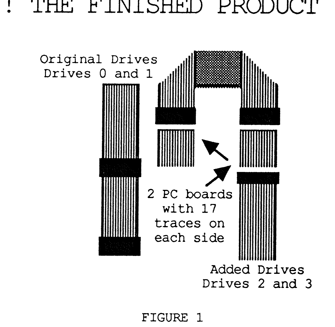
Phil had a band saw and cut a small piece of the board so that 17 traces were left on each side with a width just wide enough to slip into the two 34 pin board edge connectors. For the rest of this writing we shall call this board a cable interconnect board.
We added a Radio Shack 34 pin board edge connector to the middle of the cable of the first box and slipped one end of the little cable interconnect board into it. We then plugged the cable from the second disk drive box into the other end of the cable interconnect board. Get it? Now the two cables are in parallel!
But when we powered up, the lights on all four drive’s came on! Hey – no problem! The cable in the first box must have been built with the red tracer of the ribbon cable on pin 34 instead of pin one, right? We will just power down and reverse one of the connectors on the cable interconnect board.
We powered up again. No problem! All the lights are off. At LogiCall‘s drive prompt we entered ‘0’. Drive 0 turned and we got a CATalog but at the top it said CRC ERROR 000! We entered ‘1’ at the Program? prompt. Drive 1 turned and another CATalog with CRC ERROR 000! Drive 2 and 3 didn’t even turn! We felt the panic begin but we remained analytical. We disconnected the second drive.
We asked for CATalogs again. Both drive still gave us the same CRC ERRORs. Also, drive 1 was now making a grinding sound. We changed the disks in drives 0 and 1 for fresh ones. All was fine now! We had corrupted two disks!
Next we unplugged the first set of drives from the LarKen interface board and plugged the second set of drives. They worked fine! Hey! I thought there was a cable in this system that was made with the red tracer on pin 34 – not so if both drives work independently! The little board we made must be the culprit. Maybe the traces on the gold plated end are too close together and short out the connector. I had seen this in the past. Improperly aligned connectors in the LarKen system caused pins in those connectors not to connect to the board traces. Let’s make another cable interconnect board from a section of the board where the traces remain .1 inch the whole length of the board. Also we will be sure that it is wide enough to remain tight at the ends of the connector to insure proper alignment. It took two tries!
Phil fashioned the board and began stripping the solder resist from the foil so that the connectors would make contact with the traces. I looked into the two connectors, side-by-side, that his masterpiece was about to connect together – this time with the perfection of accuracy. ARGH! Wait a minute! This isn’t going to work! I screwed up! Pin 1 on one cable is going to connect to pin 2 of the second cable – everything is reversed! That’s why all the drives came on the first time!
Brain still working, I grabbed a short six inch long cable from the junk box with 34 pin board edge connectors on both ends and plugged it onto the cable interconnect board Phil had just completed. I put the first cable interconnect board we thought was bad into the connector on the other end. I then plugged the two cable interconnect boards into the connectors of both drives. We powered up on the RAMDISK with LogiCall – at the Drive prompt 0 – 1 – 2 – 3 – 4 – all five drives answered up with CATalogs! Voile – it all worked! See FIGURE 1 below.
Phil’s mom invited us upstairs for a dinner of broccoli soup. It was delicious! Dinner!!!? Yes – Phil and I just had just come to realize that we had blown away another perfectly good Saturday morning! [Yea, and a Sunday morning writing this article!] But because we spent the extra time to get it right, you won’t have to!!! Keep Timexin’…..
!!!! THE FINISHED PRODUCT !!!!