Authors
Publication
Pub Details
Date
Pages
“AUDISY”— Audio Digitizer/Synthesizer — is a 65 byte machine code routine that allows you to digitize and store the data for any sound phrase on your ZX/TS computer with 16K RAM. You may then synthesize the sound at will or study the data field.
AUDISY Programming Instructions
Since our machine code contains an unlistable value (code 126), it cannot be stored in an ordinary REM statement. Instead we will load the code into an unlisted REM statement located between the listed program and the display file. This requires unique USR calls referenced below the display file (the variable F).
Enter the program as follows:
- Type in a numbered REM statement containing 61 characters.
Press ENTER. - Type in the immediate mode:
POKE 16509 , 1 18 - Type in Listing 1. Press RUN and ENTER.
- Type in the decimal machine code from Table 1, going from left to right and pressing ENTER after each number.
- When all the code has been entered, delete the loader program by typing in the line number followed by ENTER. Do not use NEW or you will wipe out the code.
- Type in Listing 2, the driver program. This requires 16K.
You are now ready to use the program.
AUDISY Operating Theory
AUDISY operates as two separate routines. A call to USR (F-66) starts the digitizer (see AUDISY disassembly). First, RAMTOP is automatically lowered to location 18000 to provide a 14000 byte storage area up to location 32000. This vast field will be used to store digitized waveform data and will provide an aperature just seconds wide depending on the mean frequency stored. The higher the mean frequency, the narrower the aperature.
As the digitizer operates, register D is loaded with the value 255 and then decremented to contain 254. Register A is loaded with zero to set up the input code. If no signal is present at the input (the ear jack), the value 63 is returned by register A which causes a jump to be made to decrement D and to recycle the input loop. If a signal is present at the input, the value currently in register D is placed into the present location in the data field pointed to by the HL register pair.
A predominance of value 254 indicates a high noise level or an input signal that has a high frequency component exceeding the sensitivity of the input loop. The lower the number stored in the data field the lower the frequency that it represents. The full scale sensitivity of the digitizer is calculated to be 295 Hz to 26KHz. These are theoretical limits and are drastically reduced by such factors as noise and stray input capacitance, etc.
LISTING 1: 16K MC Routine; 2K MC Loader
  10 DIM a$(65,4)
  20 LET F=PEEK 16396+256*PEEK 16397
  30 FOR I=1 TO 65
  40 INPUT A$(I)
  50 PRINT A$(I);
  60 POKE F+(I-67),VAL A$(I)
  70 NEXT I

LISTING 2: 16K MC Routine; 16K MC Driver
 100 FAST
 105 LET F=PEEK 16396+256*PEEK 16397
 110 RAND USR (F-66)
 115 PAUSE 4E4
 120 RAND USR (F-36)
 130 GOT 120
The signal amplitude is important since any waveform not sufficiently loud will not be processed. Excessive signal, however, will cause distortion.
The synthesizer operates by addressing USR (F-36). One byte at a time, values are taken from the data field and loaded into register A which provides the timing delays for toggling the output. The output signal is provided at the mic jack on the computer and requires amplification. The Sinclair output bus is shared by the RF modulator. This means that the sound will be available over the TV audio system.
Only about 2 1/2 K of memory is left after setting RAMTOP to provide the data storage area. This limits the user’s program development. It is now possible, however, to LOAD a new program while not affecting the data stored above RAMTOP. This may prove useful when extensively processing or studying the stored data. The data field cannot be SAVEd on tape by the usual means.
Audisy Operating Instructions
After LOADing AUDISY, prepare the input source. If you choose to digitize music or voice from a cassette tape, you will have to experiment with the volume control. It will take some practice to learn to cue the tape to the beginning of the digitizer routine.
Another input source is direct microphone. Plug a microphone into the mic input of your recorder or use the built-in condenser mic, if provided. Put in a blank tape and set the cassette to record. Press pause on the recorder if you do not want the tape to advance. Make sure the ear jack on the computer is connected to the ear jack on the tape recorder.
To digitize a sound source, enter RUN while the source is playing. If the input sound is of sustained intensity, it will allow the machine code routine to cycle out and return to Basic. After running the AUDISY driver with an input signal present, the user is signalled that digitizing is complete by the brief flash on the screen as the computer goes into infinite PAUSE (line 115).
Then press any key (except BREAK) to operate the synthesizer. The synthesizer can operate repeatedly by pressing a key to interrupt PAUSE. Press BREAK and then enter RUN to digitize a new sound phrase. You may also delete line 125 for a continuously repeating playback. Remember that any time changes are made to the program listing the display file moves about. This means that the program line establishing the variable F must be entered directly or read during the program operation in order to properly reference the USR addresses.
You may hear the synthesizer output directly over the TV set. Turn up the volume and adjust the fine tuning control for the best sound. For better fidelity you may record the output on tape to be played back. Connect the mic jack of the computer to the mic jack of the recorder.
I prefer to use a small amplifier to reproduce the synthesized sound. The Archer Mini Amplifier with built-in speaker (cat. #277-1008) from Radio Shack is ideal for this project.
Table 1. Machine code data
33   4    64   54   80   35   54   70
33   80   70   22   255  21   62   0
219  254  254  63   40   247  114  124
35   254  125  32   238  201  33   80
70   22   1    126  254  254  40   15
60   254  254  32   251  211  255  126
60   254  254  32   251  219  254  21
32   233  124  35   254  125  32   225
201
Table 2. AUDISY Disassembly
The value of F
-66 LD HL, 16388         ; set RAMTOP
-63 LD (HL),80             to 18000
-61 INC HL
-60 LD (HL),70
-58 LD HL,18000          ; data field start.
-55 LD D,255
-53 DEC D                ; this loop
-52 LD A,0                 counts down
-50 IN A,254               until INPUT
-48 CP,63                  acknowledged.
-46 JR Z,-53
-44 LD (HL),D            ; store data byte.
-43 LD A,H               ; test for end of
-42 INC HL                 data field; if not
-41 CP, 125                end then find next
-39 JR NZ,-55              loc. and recycle
-37 RET
-36 LD HL,18000           ; data field start.
-33 LD D,1                ; set no. of cycles -1
-31 LD A,(HL)             ; set delay (freq).
-30 CP,254                ; disregard
-28 JR Z,-11              ; noise.
-26 INC A
-25 CP,254                ; test for end
-23 JR NZ,-26               of delay.
-21 OUT 255,A             ; turn on output.
-19 LD A,(HL)             ; set delay (freq).
-18 INC A
-17 CP,254                ; test for end
-15 JR NZ,-18               of delay
-13 IN A,254                turn off output.
-11 DEC D                 ; next cycle.
-10 JR NZ,-31
 -8 LD A,H                ; test for end of
 -7 INC HL                  data field; if not
 -6 CP,125                  end then next data
 -4 JR NZ,-33               byte and recycle.
 -2 RET
Experimenter Notes
This section deals with ways of conveniently displaying the huge data field stored above RAMTOP. The simplest routines display the data field as 218 frames of 64 byes each plotted onto the screen. Program A plots a frame at a time with a pause between. Program B superimposes frame upon frame as a possible method for observing repeating patterns. The higher frequencies are at the top, and time advances from left to right. Similarly, Program C averages samples from the data field and plots them onto one screen frame. Examples are shown to adjust ranging. Program D simulates the modulation envelope of the sound sample. Maximum and minimum values are plotted and can be altered to show the effects of filtration. Program E scrolls plotted data from the bottom of the screen. This program compresses the time scale by eliminating all bytes that contain noise (code 254) allowing easier visualization of the component waveforms. Higher frequencies are to the right, and time advances from top to bottom. It may take a while for significant displays to develop with any of these programs.
Whether you use AUDISY to characterize waveforms for voiceprint identification in a science fair project or as an amusing mimic toy, you will find this a stimulating project.
Figure 1. Program A
 1000 FOR I=18E3 TO 32E3 STEP 64
 1010 FAST
 1015 CLS
 1020 FOR J=0 TO 63
 1030 PLOT J,INT ((PEEK (I+J))/6)
 1040 NEXT J
 1050 SLOW
 1060 FOR K=1 TO 100
 1070 NEXT K
 1080 NEXT I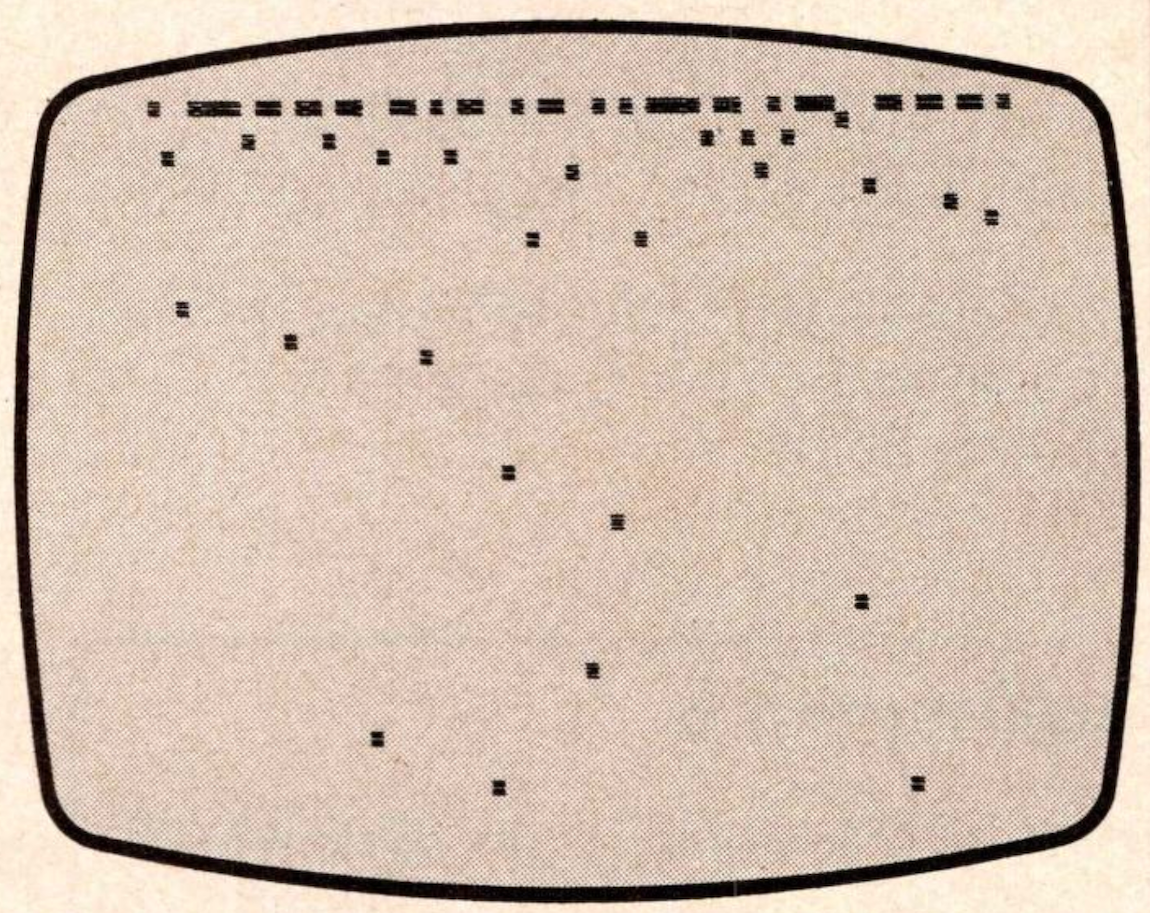
Figure 2. Program B
 1000 FOR I=18E3 TO 32E3 STEP 64
 1010 FOR J=0 TO 63
 1020 PLOT J,INT ((PEEK (I+J))/6)
 1030 NEXT J
 1040 NEXT I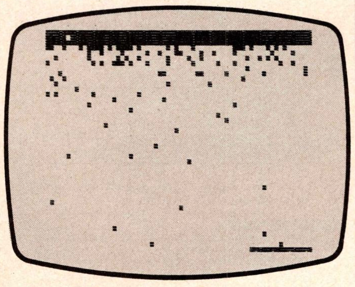
Figure 3. Program C
 1000 DIM N(10)
 1010 FOR I=0 TO 63
 1020 FOR J=1 TO 10
 1030 LET N(J)=PEEK (((I*218)+18E3)+(2*J))
 1040 NEXT J
 1050 LET A=INT ((N(1)+N(2)+N(3)+N(4)+N(5)+N(6)+N(7)+N(8)+N(9)+N(10))/10)
 1060 PLOT I,INT ((A*1.6)-363)
 1070 NEXT I

CHANGE VERTICAL RANGE FOR PROGRAM C WITH ANY OF THESE LINES
 1060 PLOT I,INT (A/6)
 1060 PLOT I,INT ((A/2.55)-56)
 1060 PLOT I,A-211
 1060 PLOT I,INT ((A*2)-465)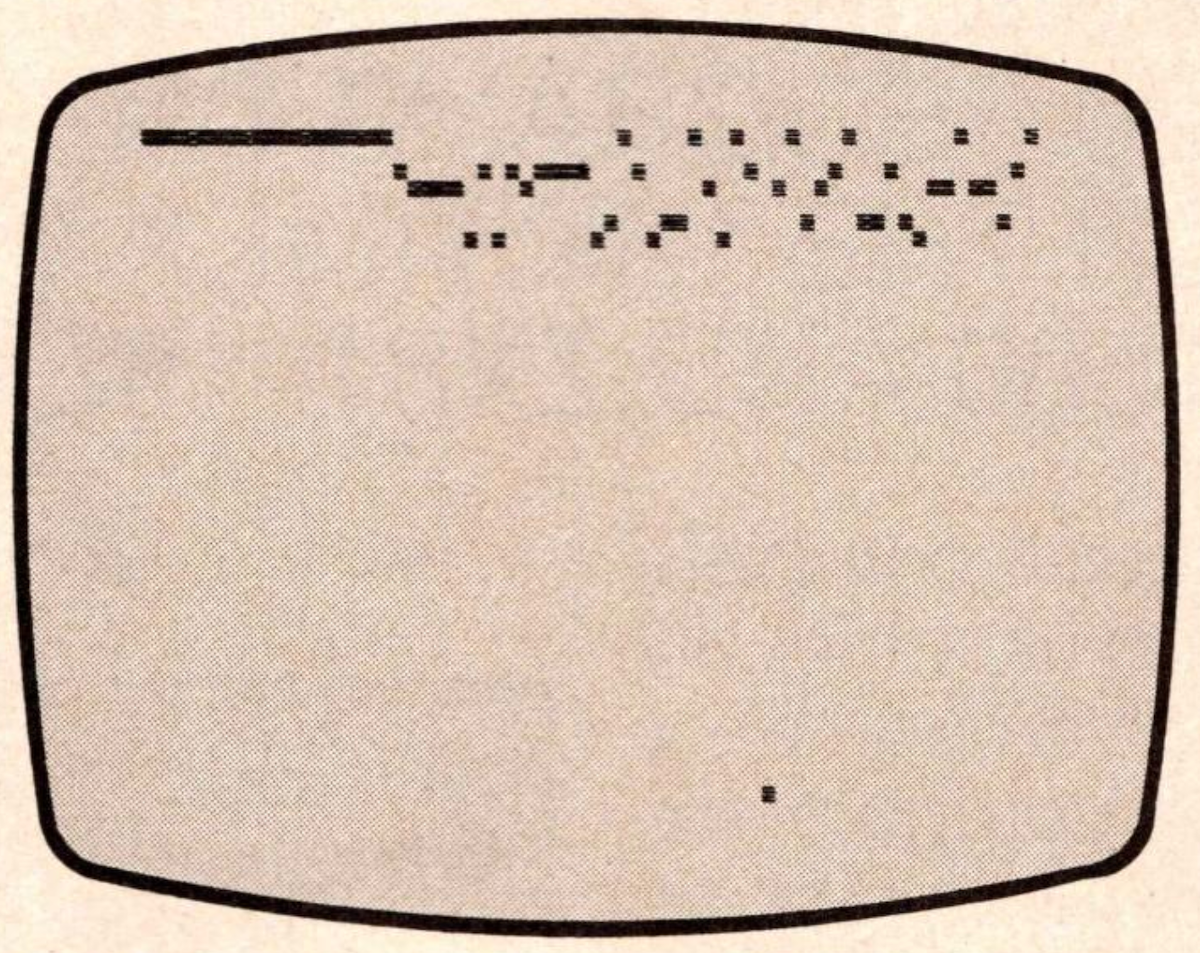
Figure 4, Program D
 1000 LET C=0
 1010 FOR I=18E3 TO 32E3 STEP 218
 1020 LET A=0
 1030 LET B=254
 1040 FOR J=1 TO 218
 1050 LET D=PEEK (I+J)
 1060 IF D>=234 THEN GOTO 1080
 1070 IF A<=D HTEN LET A=D
 1080 IF B>=D THEN LET B=D
 1090 NEXT J
 1100 FOR K=INT (B/6) TO INT (A/6)
 1110 PLOT C,K
 1120 NEXT K
 1130 LET C=C+1
 1140 IF C=64 THEN STOP
 1150 NEXT I

CHANGE LOW PASS FILTRATION FOR PROGRAM D WITH THE APPROPRIATE LINE CHANGE:

FOR NO FILTRATION:
 1060 IF D>=255 THEN GOTO 1080

FOR LOW PASS FILTRATION:
 1060 IF D>=254 THEN GOTO 1080

FOR EXTREMELY LOW PASS FILTRATION:
 1060 IF D>=127 THEN GOTO 1080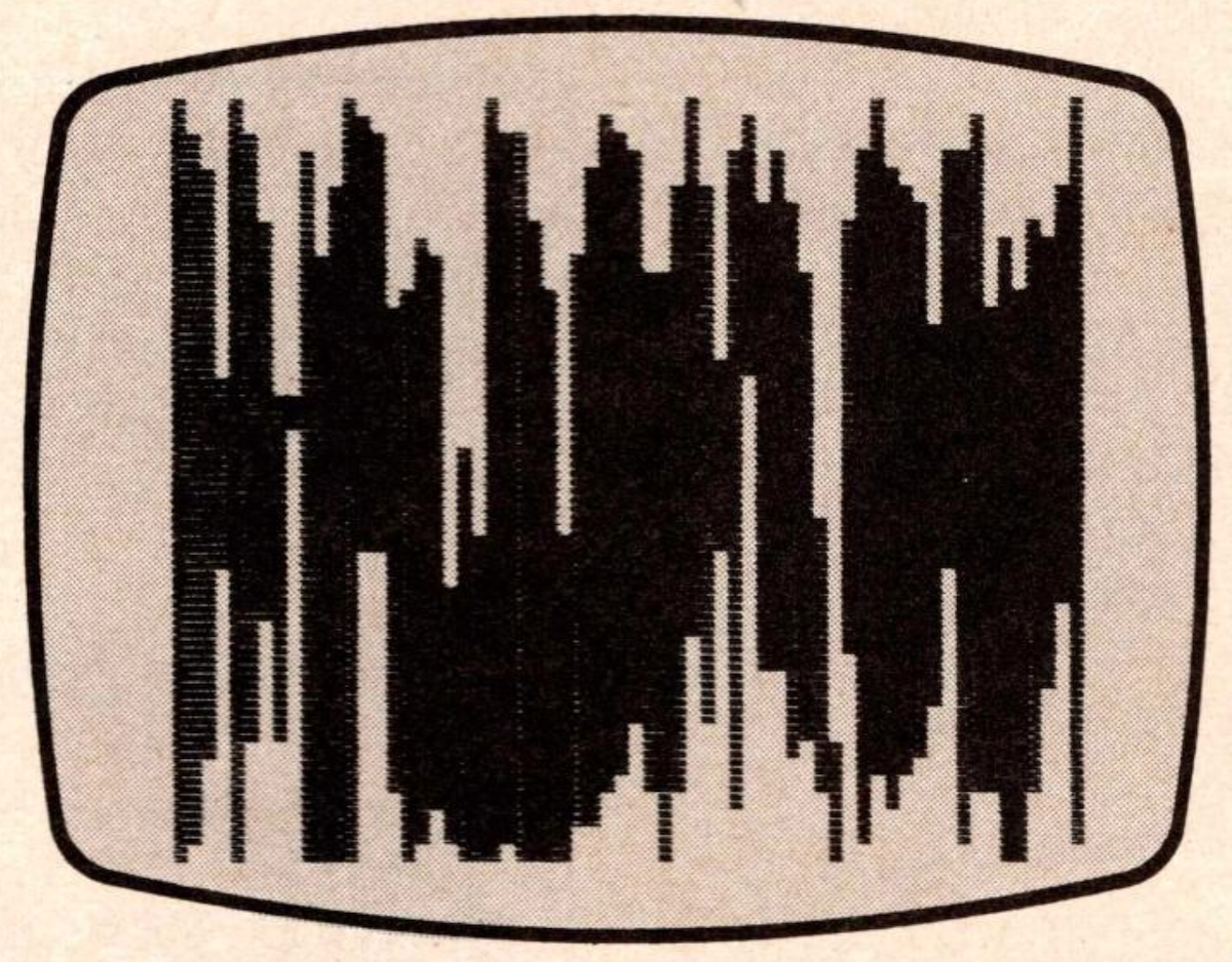
Figure 5. Program E
 1000 FOR I=18E3 TO 32E3 STEP 2
 1005 IF PEEK I=254 THEN GOTO 1015
 1010 PLOT INT ((PEEK I)/4),0
 1015 IF PEEK (I+1)=254 THEN GOTO 1040
 1020 PLOT INT ((PEEK (I+1))/4),1
 1030 SCROLL
 1040 NEXT I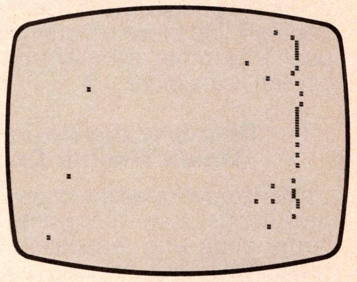
Products
Media
Image Gallery
Source Code
Note: Type-in program listings on this website use ZMAKEBAS notation for graphics characters.