
Last month in Interfacing Tips and Troubles we presented part one of a two part article on interfacing the Sinclair computers. In part one we looked at the hardware required for a simple interface, and explained how to protect memory space for storing machine language programs. This month in part two, we will present the software required to complete the interfacing task. The minimum software required to accomplish an input or an output is shown in Figure 1. In the following sections, I will discuss the software in functional blocks and explain how each block is used to accomplish the interfacing task. Remember from last month that all information in brackets [ ] refer to the Spectrum and the TS2068 computers.
Reserving Space For the Machine Language Routines
When using the TS1000 and the TS1500, line one of the BASIC program should be: 1 REM 123456789012345678. This command reserves 18 locations of protected RAM memory for storing the machine language routines. The first eight characters following the REM statement (1 through 8) occupy addresses 16514D through 16521D which will be used to store the machine language output routine. The second eight characters (9 through 6) occupy addresses 16522D through 16529D which will be used to store the machine language input routine. The last two characters (7 and 8) occupy addresses 16530D and 16531D which will be used to pass values from the BASIC programs to the machine language programs and vice versa. For the color computers, line one of the BASIC program should be: 1 CLEAR 32129. This command reserves space above the BASIC routines. Address locations 32130D through 32138D will contain the machine language output routine. Locations 32139D through 32146D will contain the machine language input routine, and locations 32147 and 32148D will be used to pass values from the BASIC programs to the machine language routines and vice versa.
Loading the Machine Language Routines
Referring to Figure 1, lines 5 through 70 of the BASIC program are used to automatically POKE machine language instructions into the space reserved by the REM statement. Line 10 sets the beginning storage location to 16514D [32130D]. Line 20 inputs a machine instruction which is entered through the keyboard. Note that the machine instructions must be in hexadecimal format. Line 30 checks to see if the character which was entered was an “S,” and if so, program execution stops. If not, line 40 converts the instruction to decimal format and POKES it in the appropriate memory location. Line 50 increments the machine language storage location and the entry process is repeated. You may be wondering why we enter the machine instructions in hex format since they are converted to decimal in line 40 before they are POKED into memory. The reason is that if we use the hex format, the instructions can conveniently be represented with two characters. Also, hex is the format that is most used by companies and authors that provide listings of machine language instructions. To execute the machine language entry program, type the command “RUN 5” and press the ENTER key. Once the program is running, input the following hex values: 06, 40, 0E, 92, 0A. D3, 00, 06, 40, OE, 93, DB, 01, 02, C9. These are the machine language values shown in Figure 1. Note: Do not enter the commas, and be sure to press the ENTER key between each instruction. When the last instruction has been input, enter an “S” to cease program execution.
Outputting To the Latch
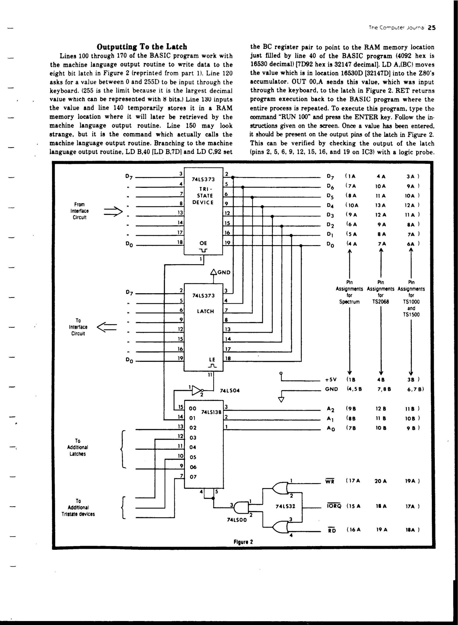
Lines 100 through 170 of the BASIC program work with the machine language output routine to write data to the eight bit latch in Figure 2 (reprinted from part 1). Line 120 asks for a value between 0 and 255D to be input through the keyboard. (255 is the limit because it is the largest decimal value which can be represented with 8 bits.) Line 130 inputs the value and line 140 temporarily stores it in a RAM memory location where it will later be retrieved by the machine language output routine. Line 150 may look strange, but it is the command which actually calls the machine language output routine. Branching to the machine language output routine, LD B,40 [LD B,7D| and LD C,92 set the BC register pair to point to the RAM memory location just filled by line 40 of the BASIC program (4092 hex is 16530 decimal) [7D92 hex is 32147 decimal]. LD A.(BC) moves the value which is in location 16530D (32147D] into the Z80’s accumulator. OUT 00,A sends this value, which was input through the keyboard, to the latch in Figure 2. RET returns program execution back to the BASIC program where the entire process is repeated. To execute this program, type the command “RUN 100” and press the ENTER key. Follow the instructions given on the screen. Once a value has been entered. it should be present on the output pins of the latch in Figure 2. This can be verified by checking the output of the latch (pins 2, 5, 6, 9, 12, 15, 16, and 19 on IC3) with a logic probe.
Inputting From the Tristate
Device Lines 200 through 280 of the BASIC program work with the machine language input routine to read data from the eight bit tristate device in Figure 2. Line 220 informs the user that he/she will be inputting a value from the interface. Line 230 initiates the inputting and line 240 branches program execution to the machine language input routine. Branching to that routine, LD B,40 [LD B,7D] and LD C,93 are set to point to the RAM memory location where the value from the tristate device will temporarily be stored. Note: 4093H [7D93H] is 16531D [32148D]. IN A,01 inputs the tristate value. LD (BC),A stores the value in memory, and RET returns program execution to line 250 of the BASIC program. Line 250 assigns the variable “A” to the value just input from the tristate device, and line 260 prints that value to the screen. This program and the output program above will continue to cycle until a break is encountered. To execute the inputting routine, type the command “RUN 200” and press the ENTER key. Again follow the instructions given on the screen. Each time the ENTER key is pressed, a new value from the tristate device will be printed on the screen. This can be verified by grounding various inputs on the tristate device (pins 3, 4, 7, 8, 18,14,17 and 18 on IC2) and observing the changing values printed on the screen.
Conclusion
So there you have it; the hardware, the software, and the list of oddities required to get you started in interfacing your Sinclair computer. The hardware and the software presented in this article cover the basics, and with this information you should be able to add the level of sophistication required to accomplish any interfacing task. Bryan, I realize that I did not answer your question about the VIC-20 EPROM programmer directly, but by using the techniques presented in this article, I think that you can modify the EPROM programmer to be used with your Sinclair color computer. Good luck, and if you have additional questions, drop us a line here at The Computer Journal We will be glad to help.
Machine Code Listing
output routine:
    06 40   LD B,40   [06 7D    LD B,7D]
    0E 92   LD C,92
    0A      LD A,(BC)
    D3 00   OUT 00,A
    C9      RET

input routine:
    06 40   LD B,40   [06 7D    LD B,7D]
    0E 93   LD C,93
    DB 01   IN A,01
    02      LD (BC),A
    C9      RET

Note: use the commands in brackets [ ] with the Spectrum and TS2068 computers.
Image Gallery
Source Code
     1 REM 123456789012345678
    [1 CLEAR 32129]
     5 REM THIS IS THE MACHINE LANGUAGE ENTRY ROUTINE
    10 LET X=16514
   [10 LET X=32130]
    20 INPUT A$
    30 IF A$="S" THEN STOP
    40 POKE X,16*CODE A$+CODE A$(2)-476
    50 LET X=X+1
    60 GOTO 20
    70 STOP
   100 REM THIS IS THE BASIC OUTPUT ROUTINE
   110 CLS
   120 PRINT "INPUT A VALUE BETWEEN 0 AND 256 AND PRESS THE ENTER KEY"
   130 INPUT X
   140 POKE X,16530
  [140 POKE X,32147]
   150 LET A=USR 16514
  [150 LET A=USR 32130]
   160 GOTO 100
   170 STOP
   200 REM THIS IS THE BASIC INPUT ROUTINE
   210 CLS
   220 PRINT "PRESS ENTER TO INPUT A VALUE FROM THE INTERFACE"
   230 INPUT X
   240 LET A=USR 16522
  [240 LET A=USR 32139]
   250 LET A=PEEK (16531)
  [250 LET A=PEEK (32148)]
   260 PRINT A
   270 GOTO 220
   280 STOP