
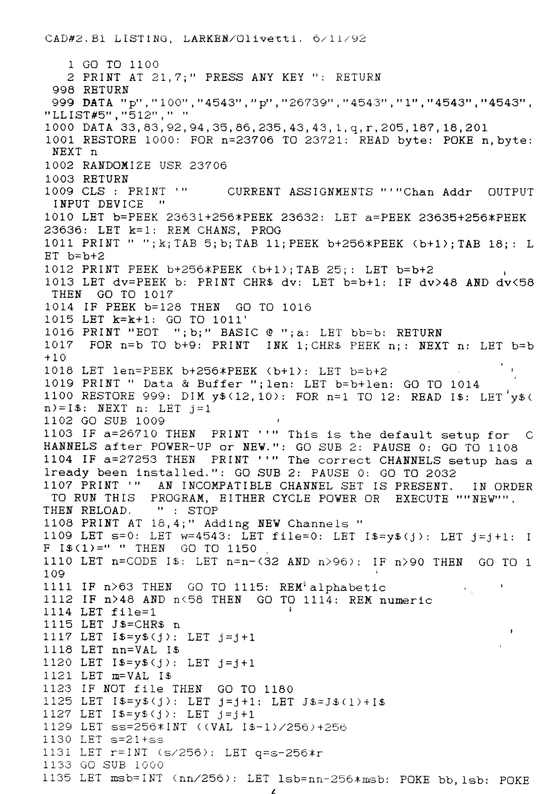
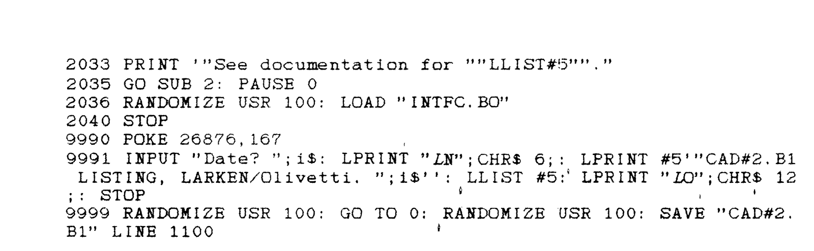
CAD#2.B1 Listing, LARKEN/Olivetti, 6/11/92 (continued from April)
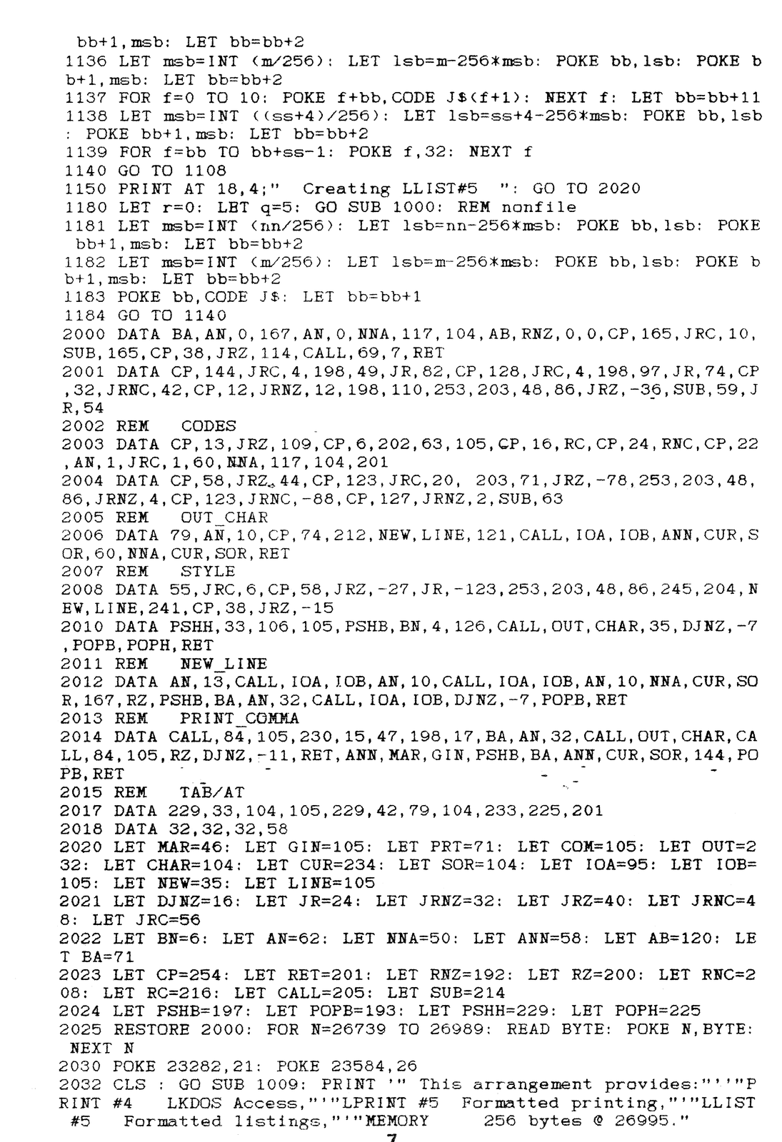
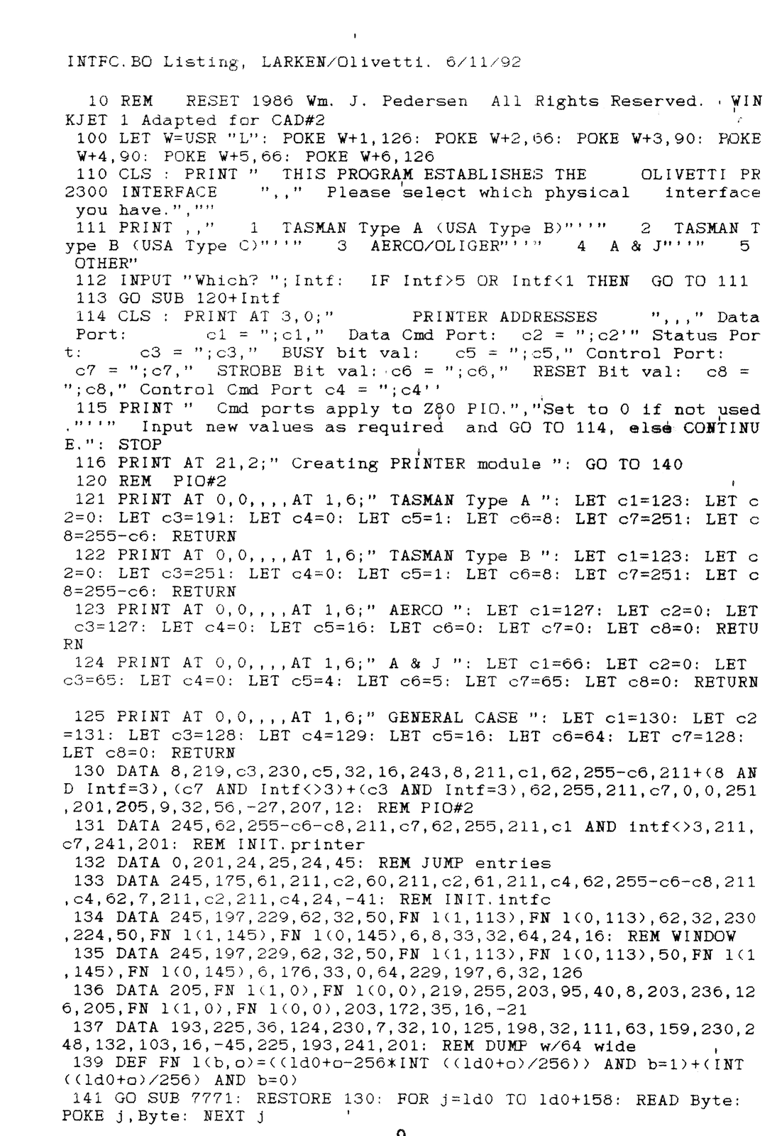
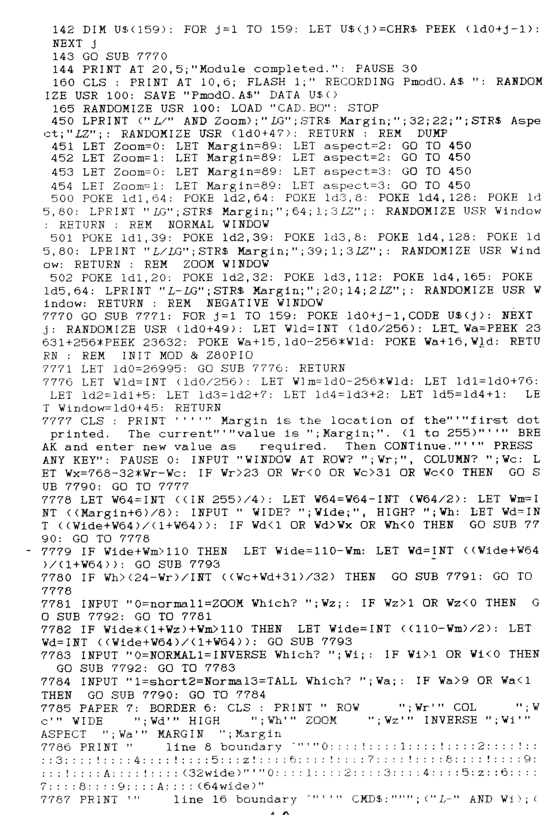
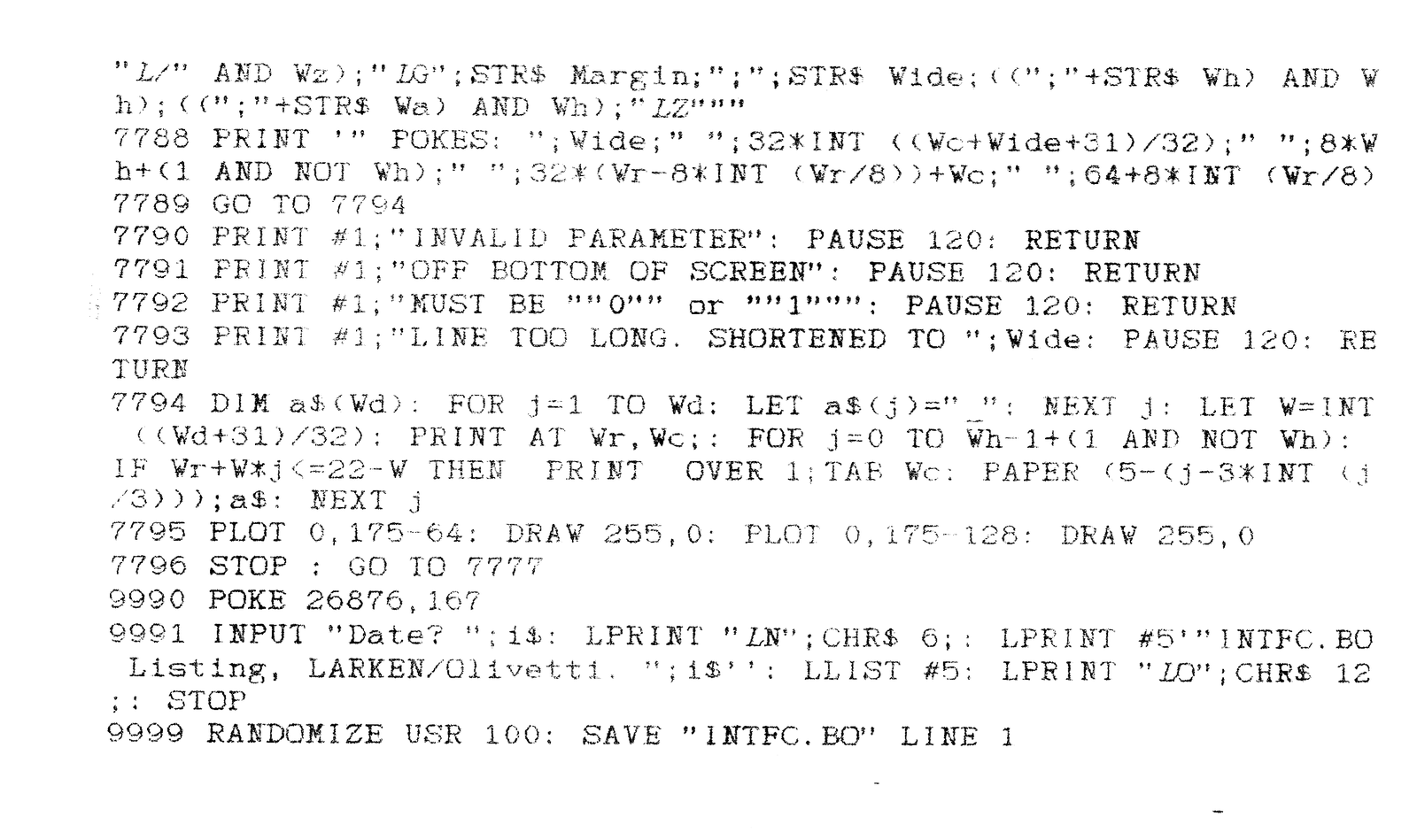
INTFC.BO Listing, LARKEN/Olivetti, 6/11/92
PRINTED CIRCUIT BOARD DEVELOPMENT PROGRAM

INSTRUCTION MANUAL    PROGRAM  CAD#2
For the OLIVETTI PR2300 INK JET PRINTER
Copyright 1989 William J. Pedersen
All rights reserved.
The WIDJUP Co. is proud to present the most powerful, flexible, and user friendly printed circuit board design program available for the TIMEX TS2068 as of this date.
It lets ambitious people create their own electronic hardware without demanding access to industrial facilities or photo laboratories.
At the same time, this program does fully professional work suitable for small industry. Though CAD#2 is self-contained, it is compatible with several specialized companion utilities like “TRACE MASTER”, which writes DATA FILES for CAD.. using higher level graphic language.
TABLE OF CONTENTS
SUBJECT                                              PAGE
---------------------------------------------------------
INTRODUCTION ..................................... 2
EXTENDED FEATURES ................................ 2
MENUS ............................................ 2
     MAIN MENU ................................... 2
     LOAD PCB DATA ............................... 3
     LOAD SUB-MENU ............................... 3
     SAVE PCB DATA ............................... 3
     EDIT PCB DATA ............................... 4
     ADD ITEM .................................... 4
     FIX MENU .................................... 5
     GENERATE .................................... 5
DISPLAY .......................................... 6
GETTING STARTED .................................. 6
TUTORIAL ......................................... 6
DEMO ............................................. 8
EDITING A PCB DATA FILE .......................... 9
EDITING GRAPHIC FILES ........................... 10
ADVANCED TECHNIQUES ............................. 12
PLANNING WORK-SHEET ............................. 12
APPENDIX ........................................ 13
     CIRCLE.AZ REPORT ........................... 13
INTRODUCTION
This program makes use of LARKEN LKDOS. This version is for the OLIVETTI PR2300 INKJET PRINTER. Other versions are available for EPSON, STAR, and some other EPSON incompatible printers. CAD#2 makes use of file types Program, Data, and Code. Files created using CAD#2 are transferable to some other DOS systems. The other system must be able to store Data type records.
Though this program assumes double density 2 sided, 5 1/4 disks, other formats are readily accommodated by changing default parameters.
All operations are menu supported, system initialization is automatic, and no LKDOS commands are required after the program is loaded.
The problem of monitoring your work as it proceeds is dealt with by a DISPLAY feature. This saves much time, paper, and aggravation.
Operations have been made as easy to use as can be, considering the complexity of the task at hand. The temptation to unnecessarily standardize operations (thus limiting what your ingenuity can accomplish) has been resisted. No compromise has been taken with quality of results. Best use of printer performance is made, though this creates a heavy computation load for the computer. If you want superior results, you have to do the work!
Exceptional editing procedures let you avoid doing work over and over again. Now THAT is user friendly!
EXTENDED FEATURES
CAD#2 provides several features in addition to what is available in LKDOS extended BASIC. To be specific, WIDJUP programs LPRINT #5, LLIST #5 (Which does formatted and indented LISTings), screen dumps, and several graphic windows for LPRINTing single and double size lines.
They say that nothing is fool-proof to a sufficiently talented fool. Well, CAD#2 has been designed to require considerable talent to foul it up, AND to recover even if it has been. Error trapping is used extensively.
DISPLAY is limited to 4 x 5.4 inches. This does not prevent making boards longer than 5.4 inches. It is simply not possible to DISPLAY the whole board at once. With advanced editing procedures this limitation becomes an advantage. (Boards wider than 4 inches can be made using wide-bed graphic printers. DISPLAY then accommodates 8 x 10.8 boards with reduced detail, but that requires a different version for that specific printer.)
MENUS
MAIN MENU
The WIDJUP Co.  (C) 1989..CAD#2
          MAIN MENU
FUNCTION       DESCRIPTION
--------------------------------
1  LOAD        PCB Data Array
2  CREATE      New PCB
3  EDIT        PCB Data Array
4  DISPLAY     PCB
5  DIRECTORY   Drives 0-4
6  REPORT      LPRINT Data
7  GENERATE    PCB Image
8  COPY        From Image File
9  SAVE        PCB Data Array

Select by # " "
This is what you see after CAD#2 is loaded. It reappears after selected operations are completed.
LOAD PCB DATA
   WIDJUP DATA LOAD SERVICE
 Drive 0
----------------------------------
 DATA ARRAYS are usually stored
 on DRIVE 0.

 Enter new drive # or simply
 ENTER to accept.

Which? " "
You may elect to keep PCB DATA files on another drive so you can use a write-protect device on your master disk. If you want to use Drive 0 and still use write-protect, you must change disks often. It is much better to have spare master disks available.
LOAD SUB-MENU
   WIDJUP DATA LOAD SERVICE
 Drive 0   WIDJUP CAD DATA
----------------------------------
DEMO.AZ     002 CIRCLE.AZ   002
NUMBER.AZ   002 ADAPT.AZ    002

LARKEN LKDOS (C)1986
Track/Side  040/002
Total Files 004
Free Blocks 058

Extension .AZ will be appended.
  ENTER to  QUIT

File name? " "
This is a directory of PCB data files from which you select by name without having to enter the file-name extension.
SAVE PCB DATA
     WIDJUP SAVE SERVICE
 Existing File is CIRCLE.AZ
----------------------------------
1  KEEP SAME NAME

2  RENAME FILE (1-6 CHR$)
     (Extension ..AZ is provided.)

3  QUIT

Select by # " "         If 2 -> Filename? " "
After creating new data, or revising old data, you can name, store or update the file. You can quit if you aren’t sure about your work – or even then, you can give it a temporary name for later attention.
EDIT PCB DATA
      WIDJUP EDIT SERVICE
 CIRCLE.AZ LAST 20   SELECT 1
----------------------------------
 1      2      3      4      5
 ¦      -      O      O      O
----------------------------------
 1      2      4      4      4
 .03    .03    1      1      1
 0      0      1      1      1
 0.2    0.2    0.4    0.35   0.3
 0      0      0      0      0
 2      2      1      1      1
 3.8    3.94   100    100    100
 2      2      1      1      1
 5.239  5.1    100    100    100
 0      0      0      1      0
----------------------------------
 EscFixSelAdd < PutCut > MapDel
 1  2  3  4- 5  6  7  8  9  0
This menu operates using ten FUNCTION KEYS labeled across the bottom of the screen. You don’t have to guess what they are, or look them up in a manual. SELECTED data and adjacent ITEMS are displayed.
ADD ITEM
      WIDJUP EDIT SERVICE
----------------------------------
 1  ¦  Line        7  /  Jog
 2  -  Line        8    Jog
 3  =  Box         9  ?  Slant
 4  O  Circle     10  #  Pad
 5  /  45 deg     11  #  Pad
 6    45 deg     12  $  Quadrant

  Items oriented as they appear
 DISPLAYED, not as printed.

Select by # " "
The sprite characters shown above are not quite what appears on screen. The actual screen displays UDGS which cannot be printed using ASCII CHR$s.
Each item has a default which saves entry time and helps avoid errors.
It is planned to increase this library in the future, but it is hard to predict what might be wanted that isn’t already there.
FIX MENU
      WIDJUP EDIT SERVICE
   DATA ENTRY AND MODIFICATION
                  ITEM # 1  ¦
0  CANCEL
  1  At X=        .03
  2     Y=        0
  3  To Y=        0.2
  4 Width=        .06
    -----         0
  6 Y copies..    2
  7 Y Pitch       3.8
  8 X copies..    2
  9 X Pitch       5.24
 10 Eraser..      0
11 INSTALL

Select " "
An ADD, or SELECTED existing item is displayed in a format unique to each “sprite”. Any parameter can be selected and changed. You can QUIT or INSTALL the results of your work. If you make an error, you can always recall the item to correct it.
This menu returns you to the EDIT menu.
GENERATE
    WIDJUP GENERATE SERVICE
----------------------------------
 0  QUIT
 1  Screen Only
 2  LPRINT
 3  FILE
 4  LPRINT & FILE
----------------------------------
  Mode is #...    [after select]

  0.xxx Scale will print an
 overlay matching REPORT.

Select by # " "     If 1 or 2 -> Scale? " "
                    If 3 or 4 -> New or Update? " "
                                 If New -> Scale? " "
This menu really has the choices you want. It is possible to PRINT and/or FILE graphic images of the PCB in exquisite detail in any scale.
What is remarkable is how you can edit GRAPHIC FILES without needing to regenerate them.
This feature allows you to create a library of graphic MASTERS for standardized cards.
(A WIDJUP program is available for GENERATING logos, text and component designations. That program is intended for making silk-screen masters, but can be used to add similar detail on copper as well.)
DISPLAY
When called from the MAIN menu, this draws a picture of the PCB using symbols and lines. The real PCB has too much detail to show on the screen, even if windowed. The display is completely independent of scale factor, which would also make windowing difficult.
When called from the EDIT menu, this draws a picture of the SELECTED item. This lets you try what you please, and get it exactly right. There is no need to wait for a GENERATED image to find you have to make a change.
When called by REPORT it displays and prints a PCB image in hard copy for you.
GETTING STARTED
1. It is assumed you have an LKDOS or equivalent disk system for your TS2068 and at least one disk drive. Two drives are required to get the most out of CAD#2, but one drive will do.
2. RANDOMIZE USR 100: LOAD “CAD#2.B1” after power-on, NEW, or use of LKDOS FORMAT or Move operations will call up the program.
3. An information display will appear on the screen that shows which channels are in use. If the power has just been turned on, or NEW executed, this will be TS2068 default assignments. If called after LKDOS operations, it may show those channel assignments too.
Press any key after you examine this screen.
If LKDOS assignments have been made which are incompatible with CAD.#2 you will get a warning message.
4. The next screen shows channel assignments used for CAD#2 after initialization. Flashing labels appear while these channels are being created and extended function features are initialized.
After examining this screen, press any key to continue.
5. The next screen to appear is from another program called by the first. It permits you to select from TASMAN, AERCO, OLIGER, A & J, or custom CENTRONICS interfaces. After selection (or a custom interface specification), a printer interface module is built to handle your hardware requirements. This is stored on disk for recall at any time by other programs.
6. After the printer module has been completed, the working program CAD.BO is automatically called. “INITIALIZING” appears while CAD.BO loads arrays, UDGS, and the printer module.
After this work is done, the MAIN MENU appears.
7. You are now in business. In spite of the complexity of this start-up sequence, all you had to do was select your interface.
TUTORIAL
In order to make it easy for you to become familiar with how this program works, several examples have been included on the master disk along with operating programs and data. The sample PCB DATA records are:
DEMO.AZ, CIRCLE.AZ, NUMBER.AZ and ADAPT.AZ.
Select DIRECTORY (5) from the MAIN MENU and then DRIVE 0 from the DIRECTORY MENU. You will see the MASTER disk directory. Pressing any key returns you to the MAIN MENU.
If you have a second drive, now is a good time to put a disk in it and repeat the selection using drive 1.
On leaving DIRECTORY SERVICE, control is always restored to DRIVE 0.
Now, with the MAIN MENU on screen, is a good time to demonstrate the screen dump feature. Instead of entering a selection number, enter “Q” or “q”.(QUIT) This returns you to Sinclair BASIC. CONTINUE will usually return you to CAD.BO depending on what you do in BASIC. GO TO 1 will always work. Though RUN works too, all your working data is lost and the program has to re-initialize itself.
GO SUB DUMP will copy the screen to your printer. GO SUB DUMP+1 will do the same, only twice as large. This works for any screen (except auto-listings) after breaking out into BASIC. Escape into BASIC has other uses, which will be discussed later when the subject is editing GRAPHIC FILES.
Try entering these immediate commands before proceeding. Then enter GO TO 1 to return to the MAIN MENU.
Select LOAD (1) from the MAIN MENU. You will be asked which drive you wish to use for storing PCB DATA FILES. These files have extension .AZ. Because the sample files are on the master disk, press ENTER to accept default DRIVE 0.
A directory of all DATA FILES appears. You will be asked to select which of them you wish to load. It is not necessary to type the file-name extension. Type CIRCLE and ENTER. Press any key to return to the MAIN MENU.
Select DISPLAY (4) from the MAIN MENU and a picture of CIRCLE will be drawn on screen.
Select REPORT (6) from the MAIN MENU. The same thing will happen except the picture will be dumped to the printer followed by a complete report of the “sprites” which make up CIRCLE. This report is graphic so you can see UDGS which cannot normally be printed. This hard copy report makes it much easier to edit your work at leisure, away from the screen.
Select GENERATE (7) from the MAIN MENU. An OPTIONS MENU appears.
Select LPRINT (2) from the OPTIONS MENU because we don’t want to create any GRAPHIC DATA files as yet. You will be prompted to enter the desired scale factor. Enter a value of 0.5 to get a half scale printout.
This will take some time, but the process is well worth watching.
The vertical resolution of the OLIVETTI PR2300 printer is 216 scan lines per inch.
The horizontal resolution is 110 dots per inch.
It takes four SCREEN lines to map one eight-line printer pass. The screen displays three lines of 256 pixels (768 total) plus a partial line of 112 pixels to match the 880 dots on a printer line. This pattern of four lines is repeated twice more on the screen to make up the three passes needed for the printed line.
Even at half scale you can appreciate the precision that is possible using this program. Even smaller scales can be used to get a quicker look at your work without creating a file.
PCB photo masters are usually done with a scale factor of 2. On occasion, a factor of 1 is used for silk screen masters, solder masks, and contact print transparencies. By adjusting the scale to match photocopy reductions, good transparencies can be made without the services of a photo laboratory — saving $$$$. Then you can use them with photo-etch kits available from RADIO SHACK and others.
Before proceeding, if you have only a single drive, enter “Q” or “q” at the MAIN MENU. Then LET Gdrive = Drive. Remove the master disk, replacing it with a blank formatted one.
Remember not to use RUN to return to the MAIN MENU. Use GO TO 1.
If you have two or more drives, place the disk in DRIVE 1. You don’t have to remove the master disk unless it makes you feel safer that way.
Write protect tabs are a good idea if you decide to keep your PCB DATA files on other than your master disk. Always make a copy of your master disk –in fact make several. That way you can keep a disk set for every large project you tackle.
Select GENERATE (7) from the MAIN MENU. This time select FILE (3) from the OPTIONS MENU. A new prompt appears, asking you if you wish to create a new file or update an existing one. There is no GRAPHIC FILE for CIRCLE so enter “N” or “n”. You can enter NEW if you want, but only the first letter matters.
Then enter 1 at the “Scale?” prompt and find something else to do while the computer is busy creating a GRAPHIC FILE of CIRCLE.AZ. For simple files like-CIRCLE the wait is not very long. A highly complex circuit board may take up to three hours and generate hundreds of records. This is seldom required because GRAPHIC FILES can be EDITED as the job proceeds.
When the file has been completed, return to the MAIN MENU and use DIRECTORY to examine the results. You will see that the records use the first three characters of the DATA FILE name followed by numbers in ascending order and the extension .CZ.
Note the number of the last record. It is the number of printer lines.
Return to the MAIN MENU and select COPY (8). You will get a directory of the GRAPHIC FILE and asked to enter the file-name. Only the first three characters matter. This lets you do magical things like joining several different graphic files to make a single photo master.
Type in CIRCLE and ENTER.
You are prompted to enter the number of the last record to be copied. Use the number of the last record shown on the screen. Later on, you will find-how to use other values to get repeating patterns for longer boards, but for now we want to print the complete file.
The records are read in one by one and printed as fast as the printer can accept the data.
DEMO
Now put in the first of the two DEMO IMAGE disks in place of the one you just created. COPY this file to the printer after aligning the paper as you did for CIRCLE. The DEMO file has 93 records which exceeds the capacity of a single disk. It is a full page size file.
After printing 76 lines, you will be prompted to install the second DEMO disk and enter “GO” when ready. In this case you must use upper case letters exactly two characters long as shown. This guards against accidentally striking keys while you are changing disks.
DEMO contains examples of “sprites” of all kinds and two kinds of graphic file editing. It demonstrates the importance of having erasers to complement drawing. Any “sprite” can be repeated as an array, making DIP patterns a single feature ITEM.
Nearly all CAD programs provide 45 degree diagonal lines. Very few provide slanting lines at other angles. This limits the efficient layout of conductor traces. Draftsmen are used to using tape and rub-on supplies to create layouts. One form of rub-on line has rounded ends so it doesn’t matter at what angle a direction change is made. CAD#2 is nearly unique in providing a “sprite” which gives round ended line performance. The same used as an eraser allows other “sprites” to be clipped at any angle.
An explanation is required as to why “sprites” has been enclosed in quote marks. This will not be done hereafter.
A sprite is most commonly a pattern of dots called a bit-map. In this form a sprite can be repeated and moved very efficiently for games and for graphic drawing where precision is not critical. It does not matter if an engineering drawing, or circuit diagram is exactly to scale. On schematics a capacitor or resistor symbol has initially been created as a bit-map to the appropriate scale and need not be re-drawn. This is also true even of fonts generated by algorithms. They are drawn once but used many times.
A printed circuit board DOES require precision. If everything on the PCB was on a .1 x .1 grid, the OLIVETTI dot spacing would be 11 x 21.6.
21.6???? How do you print .6 of a dot? You could round this off to print a bit-mapped sprite at dot 21 or 22, but the irregular spacing is sure to create problems. This limitation of bit-mapped sprites is too serious to allow their use when better methods are available.
The sprites used by CAD#2 are two dimensional versions of those used in flight simulator programs, but the image generating technique is different.
They are defined as figures in real space, not as dot patterns. To print these images as dots, the printer dot grid is overlaid on real space. Those grid points which overlay real figures get printed. The others don’t.
It is easy to show that statistical error is much less than for bit-mapped sprites and is essentially independent of PCB feature location. Non-decimal spacings for some connectors and conductor traces are easily accommodated. Repeated sprites often do not have identical bit-maps because the printer dot grid does not match that in real space for the board. This lets sprites be as accurate as possible at any position. Rounding errors on one scan line are averaged by adjacent scans, making the pattern rendition much closer to true position than a single dot. These slight edge irregularities are barely visible and are smoothed even further by the etch process.
That is why extra effort has been spent in computation. The results are worth it. DEMO should convince you of that. A full description of DEMO is too long to include here. It is suggested that you LOAD DEMO and print a REPORT for it, as you did for CIRCLE.
EDITING A PCB DATA FILE
LOAD (1) CIRCLE as you did before. We will now edit this file in two ways. We will ADD a new feature. Then we will CUT a MACRO FEATURE from another file and PASTE it to CIRCLE.
Select EDIT (3) from the MAIN MENU. The EDIT screen will appear with the first five ITEMS of CIRCLE displayed. The first item appears in red because it is SELECTED, as also shown in the heading. The heading shows the file-name and total number of ITEMS in the file as well.
Across the bottom of the screen is a command line showing what each FUNCTION KEY does. To activate a FUNCTION KEY, press SHIFT and any number key. The corresponding operation will be performed.
KEY LABEL   FUNCTION

1   ESC     Return to MAIN MENU
2   FIX     Edit SELECTED ITEM
3   SEL     SELECT a different ITEM
4   ADD     Append a new ITEM
5   <-      SELECT ITEM to the left
6   PUT     PASTE stored ITEM just before SELECTED position
7   CUT     CUT and store SELECTED ITEM
8    ->     SELECT ITEM to the right
9   MAP     DISPLAY SELECTED ITEM
0   DEL     DELETE ITEM without storing
Hold the SHIFT key down and then press the 4 key. A menu of pre-defined sprites will appear. There are 12 choices, each of which has default values which can be edited to meet your needs. This helps avoid errors of omission when entering parameters.
Select sprite # 10. This is a DIP pad array by default. A new screen appears showing default parameters for the selected sprite. We will not change any values, accepting the default for now.
Select “G” (GO) from this menu. The EDIT menu will reappear with our new sprite SELECTED.
Use FUNCTION KEY “ESC” (s1) to return to the MAIN MENU.
Select DISPLAY to see what has happened.
Select SAVE and rename the file TEST so CIRCLE will not be changed.
You can verify the file has been saved using DIRECTORY.
We have just added an ITEM to a file. Now we will do something more interesting. We will transfer ITEMS from one file to another. In this case we will transfer three ITEMS which make up the graphic character “1” from NUMBER to TEST.
Select LOAD from the MAIN MENU and load NUMBER.
Select EDIT.
Command "SEL", enter 3.  ITEM #3 is now selected.
"CUT".  ITEM #3 is deleted and stored in the cut file
"ESC" and press any key.
LOAD TEST, Select EDIT
"SEL" 1, "PUT".  The stored cut ITEM is inserted as ITEM #1.
"ESC", SAVE TEST.  (With updated data.)
Repeat this sequence for ITEM #2 and #1 from NUMBER to TEST.
By now you should be getting familiar enough with CAD#2 to allow us to abbreviate instructions as shown above. DISPLAY your updated TEST to see how these new sprites look. It is possible to recognize the graphic number “1”, but DISPLAY cannot generally render such small detail in a form which can be recognized.
GENERATE TEST to the printer using 0.5 scale. Now you can see the final results of your editing operation. Repeat using .25 scale to see how detail is slowly lost as scale is reduced. When checking your work, this is not objectionable in most cases. Use as small a scale as you can accept.
EDITING GRAPHIC FILES
You have GENERATED a GRAPHIC FILE from CIRCLE.AZ. That file has record names CIR1.CZ, CIR2.CZ and up. Only the first three characters of the DATA FILE name have been copied.
Another DATA FILE named CIRC#1.AZ would GENERATE the same record names, obliterating the old file.
Instead, if CIRC#1.AZ is used to UPDATE an existing file, we have a perfect mechanism for editing GRAPHIC FILES.
An application which comes immediately to mind is to have a set of DATA FILES all having the first three characters in common. The first could be the edge contacts and basic circuit arrangement for a family of similar boards. A second could define the hole patterns and pad layout. A third could define conductor traces, targets, and other features.
The first DATA FILE could be used to make as many copies of the basic GRAPHIC FILE you might want. Then one of these can be UPDATED to define hole patterns to make new files representing two sides of the same board. Then other files could be used to add circuitry, pads, text, and other features for each side of the board.
LOAD NUMBER  (from master disk)
SAVE NUMBER, renaming it CIRNUM  (does not replace NUMBER on disk)
Place the CIRCLE GRAPHIC FILE disk back in the drive.
GENERATE using FILE and UPDATE  (LPRINT optional)
The program loads a GRAPHIC RECORD so it can read what scale to use. Then it updates only those frames effected, scanning through but not changing intermediate records. If LPRINT was also asked for, only these same frames will be printed.
COPY the resulting merged file. You will see that all numbers from 1 thru 0 have been transferred to the GRAPHIC FILE.
THIS ENDS THE TUTORIAL.
ADVANCED TECHNIQUES
There are 432 scan lines or 18 printed lines to the inch referred to double scale photo master layouts. This is also 18 records in a GRAPHIC FILE. When GRAPHIC FILES are COPIED, they continue without any gaps between them. One file could contain one end of a PCB. A second could contain the other end of the board and a repeatable pattern of 9, 18, 27 etc. records.
The first file can be copied in full. It should be a multiple of 9 lines in length or copied to that number. An overlap zone is optional.
The second file can be copied using the repeat portion as many times as necessary, then the repeat portion plus the end of the board.
You can erase portions of a board layout to correct errors, or to edit text, logos, or part numbers. This applies nicely to circuit variations which make use of alternate jumpering to adapt a board to varying conditions like I/O address assignment.
PLANNING WORK-SHEET
The master disk contains GRID.BO which generates work-sheets for use in planning and editing your jobs. Call it after breaking in on CAD.BO. To return, bypass CAD#2.B1. Reload CAD.BO. (Or use the SHELL provision.)
U$ is a machine code image of the OLIVETTI printer driver. It is installed as an overlay from within the program. Though not applicable here, this method allows changing printers on the fly. It consists of three parts. The root section is for matching to various physical interfaces, like AERCO, TASMAN etc. An initialization section primes whatever interface you are using. The third section is the GRAPHIC DRIVER. This is the part which matches up the screen with the printer. It does windows.
By POKING values, this driver will do many kinds of normal, or zoom WINDOWS, printing to the full width of your printer.
Program modifications to accommodate other disk formats and other special information is provided separately because updates occur which do not effect program operations, but which may change line numbers and content appreciably. These modifications refer to specific revisions of CAD#3 and are cumulative over time.
The WIDJUP Co.
1120 Merrifield S.E.
Grand Rapids, MI 49507
Tel: (616) 452-7004