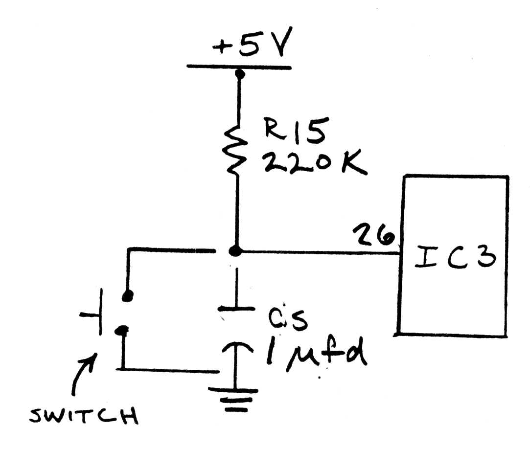
One of the noted short-comings of the TIMEX-SINCLAIR TS1000/ZX81 is the lack of an “off-on” switch. I’ve found that adding a simple “reset” switch to the computer gives me the same end result as an “off-on” line power switch and it has the added benefit of less wear and tear on the power input jack.
Adding a “reset” switch is really one of the simplest and most inexpensive (read cheap) first additions an owner can make to his computer.
In any modifications I give instructions for, I usually specify Radio Shack catalog numbers simply because Radio Shack outlets are accessable to more people than other national suppliers. The fact is that there are a lot of first-time computer owners that will feel more comfortable with specific part numbers, supply sources, and simple instructions. Let’s face the fact that not everyone who owns a computer can make successful hardware modifications using “paper clips and alligator clips.” I will try to make all my instructions as “goof-proof” as possible but remember I can’t be responsible for any damages to your machine.
PROCEDURE
First disconnect all cables from the unit and turn it over. Next remove the three rubber pads covering three of the five case screws. I usually just stick them to the case toward the center so I don’t lose them. Otherwise they get dirty and won’t restick.
Now remove the five screws that you can see; be sure to use a good phillips-headed screwdriver since you will be removing and re-installing these same screws many times as you modify your computer. Remove the cover and set it aside. I place the removed screws in the turned-up case to keep track of them.
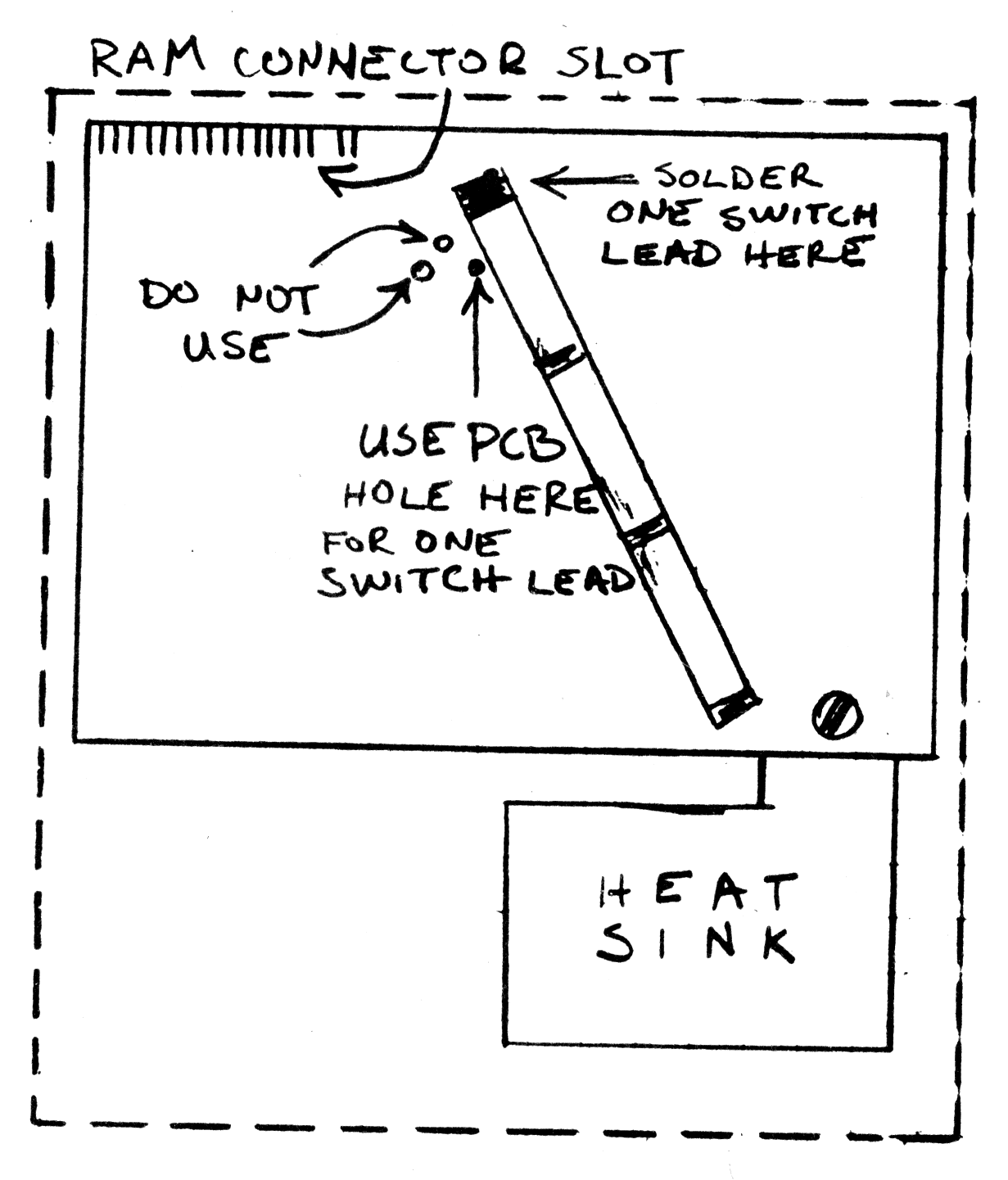
Now while looking at the bottom side of the PCB, you will see the raised metal strip going diagonally across the PCB. Apply a soldering iron to the end nearest the RAM expansion edge connector while giving a slight upward pull with a pair of needle-nose pliers; in a few seconds the end will come free. Lift the free end gently and brace it up out of the way (I used a flat rubber eraser). Now you should have a view as in figure 1. Set the unit aside and prepare your switch. I used the Radio Shack catalog no. 275-1547 which comes five to a package. It is a Mini SPST NO (normally open) momentary contact with solder lugs. Prepare two 2-inch lengths of wire (R/S Cat. No. 278-1307-package of 3 color); it is best to use two different colors for later identification. Solder the wires to the switch; prepare the wires to mount into the PCB. Note at this point the more experienced builder will probably take out the two PCB screws and carefully move the PCB out of the way to drill and mount the switch in the rear of the case. If you do this be careful to avoid hitting any of the PCB components and make sure you don’t pull out the flat keyboard cables. After you have decided on mounting or not mounting the switch proceed to the actual solder attachment to the PCB. Refer to figure 1. Solder one of the wires to the indicated point (it doesn’t matter which wire is used). Be neat and clean. If you have used #22 wire it should fit in the PCB hole easily. Now remove the rubber eraser letting the metal strip again rest on its original mounting pad. Place the remaining wire lead on the strip and resolder the connection. Replace the bottom half of the case. Plug in the computer and fire it up. A cursor should appear as normal (If it doesn’t, remove the bottom and check to see if you have loosened the keyboard flat cable). Now press the switch. The cursor should disappear for a few seconds and reappear after the computer has reset all the registers to zero and run its internal RAM check routine. There it is: two simple solder connections and you have a useful addition to your computer.