This subroutine defines six User Defined Graphics (UDGs) by poking checkerboard bit patterns into UDG memory to simulate ZX81/TS1000 gray block graphics. It uses RESTORE to point to line 9100 — note this targets a non-existent line, so execution falls through to the DATA statements beginning at line 9050. Each UDG is defined by eight bytes of alternating bit patterns (170 = 10101010 binary, 85 = 01010101 binary) in various combinations that produce different densities of dithered fill. The six patterns range from a 50% checkerboard (“A”), through half-filled variants (“S”, “D”), inverse checkerboards (“F”, “G”, “H”), effectively giving a palette of gray shades for block graphics work. The REM statements at lines 9001–9003 document a full 21-character UDG assignment scheme (A through U) as a reference guide, though only six are actually programmed here.
Program Analysis
Program Structure
The code is organized as a self-contained subroutine designed to be called with GO SUB 9000 from a host program. Lines 9000–9003 are documentation REMs. Lines 9010–9045 implement the loading loop and RETURN. Lines 9050–9055 hold the DATA for six UDG definitions.
- Lines 9000–9003: REM comments documenting purpose and full UDG letter map (A–U).
- Line 9010:
RESTORE 9100— targets a non-existent line, so the DATA pointer falls through to the first DATA statement at line 9050. - Lines 9015–9040: Nested loop reads a letter and eight bytes, then POKEs each byte into
USR c$ + a. - Line 9045:
RETURNends the subroutine. - Lines 9050–9055: Six
DATAstatements, each supplying a UDG letter and eight pixel-row bytes.
RESTORE Targeting Technique
RESTORE 9100 references a line that does not exist. The interpreter advances the DATA pointer to the next available DATA after line 9100, but since all DATA lines are below 9100 (9050–9055), this effectively resets the pointer to the very first DATA in the program. This is a deliberate technique to ensure the correct DATA is read regardless of any prior READ calls elsewhere in the host program.
UDG Definition Method
The outer loop (c, 1 to 6) iterates over the six UDGs. For each, a letter string c$ is read, then eight byte values are read and POKEd into USR c$ + a where a runs 0 to 7 — addressing each of the eight pixel rows of that UDG’s 8×8 bitmap.
Dithered Gray Patterns
The bit patterns are constructed from 170 (binary 10101010) and 85 (binary 01010101), which are perfect complements. Combined in various ways across the eight rows, they create six distinct dithered fills:
| UDG | Pattern Description | Bytes (rows) |
|---|---|---|
A | Full 50% checkerboard | 170,85 alternating × 4 |
S | Checkerboard top half, black bottom | 170,85 × 2, then 0 × 4 |
D | Black top half, checkerboard bottom | 0 × 4, then 170,85 × 2 |
F | Inverse checkerboard top, solid white bottom | 85,170 × 2, then 255 × 4 |
G | Solid white top, inverse checkerboard bottom | 255 × 4, then 85,170 × 2 |
H | Full inverse 50% checkerboard | 85,170 alternating × 4 |
Note that A and H are pixel-complementary — together with S/D and F/G, the set provides vertically split half-density variants useful for smooth shading gradients in graphics routines.
Notable Techniques
- Reading the UDG letter as a string and using
USR c$avoids hardcoding memory addresses, making the subroutine portable across different memory configurations. - Placing all subroutine code in the 9000-range keeps it neatly separated from main program logic.
- The REM lines 9001–9003 embed a visual UDG reference chart (letters A–U mapped to UDG symbols) directly in the source, serving as inline documentation for the developer.
- Using a single nested loop with a string variable for the UDG name allows arbitrary reassignment of which letters receive which patterns, as noted in the line 9000 comment.
Observations and Potential Issues
- The outer loop variable
cis also used as the loop counter, while the UDG letter is stored inc$— the reuse ofcas both loop index and a meaningful name could cause confusion when reading the code. - Only six of a possible 26 (A–Z) UDG slots documented in the REMs are actually loaded; the remaining slots retain whatever values were previously in UDG memory.
- The
RESTORE 9100technique relies on no DATA lines existing between 9100 and the end of the program above 9050; adding DATA in that range would silently break the routine.
Content
Image Gallery
Source Code
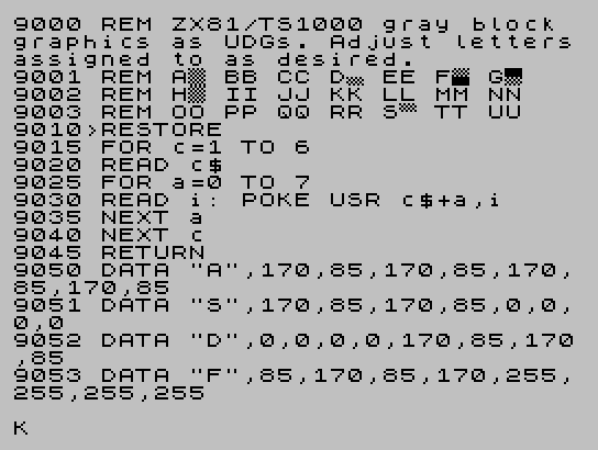
 9000 REM ZX81/TS1000 gray block graphics as UDGs. Adjust lettersassigned to as desired.
 9001 REM A\a B\b C\c D\d E\e F\f G\g
 9002 REM H\h I\i J\j K\k L\l M\m N\n
 9003 REM O\o P\p Q\q R\r S\s T\t U\u
 9010 RESTORE 9100
 9015 FOR c=1 TO 6
 9020 READ c$
 9025 FOR a=0 TO 7
 9030 READ i: POKE USR c$+a,i
 9035 NEXT a
 9040 NEXT c
 9045 RETURN
 9050 DATA "A",170,85,170,85,170,85,170,85
 9051 DATA "S",170,85,170,85,0,0,0,0
 9052 DATA "D",0,0,0,0,170,85,170,85
 9053 DATA "F",85,170,85,170,255,255,255,255
 9054 DATA "G",255,255,255,255,85,170,85,170
 9055 DATA "H",85,170,85,170,85,170,85,170
Note: Type-in program listings on this website use ZMAKEBAS notation for graphics characters.