
Nodes draws a fully connected graph by distributing a user-specified number of nodes evenly around a circle and then drawing a line between every pair of nodes. The node positions are calculated using trigonometric functions, placing each node at angles of 2π·i/n radians around a center point at (15, 8) in BASIC coordinate space with a radius of 4 units. A scale factor entered by the user multiplies all coordinates before each PLOT and DRAW call, allowing the diagram to be resized to fit the display. The outer loop iterates over each node n, and the inner loop runs from n+1 to the total node count, ensuring each pair is connected exactly once without duplication. Arrays x() and y() are pre-dimensioned to 60 elements, setting an upper limit on the number of nodes the program can handle.
Program Structure
The program is organized into three clear phases: initialization and user input (lines 10–90), coordinate pre-calculation (lines 100–140), and rendering (lines 150–260). Two arrays, x(60) and y(60), are declared at lines 10–20 to hold the Cartesian coordinates of up to 60 nodes. A SAVE statement at line 270 with LINE 10 stores the program with an auto-run start point.
Coordinate Calculation
Node positions are computed in the loop at lines 100–140. The angle for node i is calculated as z = 2 * PI * i / in, distributing nodes uniformly around the full circle. The center of the circle is placed at (15, 8) in unscaled BASIC coordinates with a radius of 4 units, using SIN for the x-component and COS for the y-component. All coordinate values are stored in the arrays before drawing begins, avoiding repeated trigonometric computation during the rendering pass.
Rendering Algorithm
The complete graph is drawn using a nested loop structure at lines 160–240. The outer loop variable n runs from 1 to im (which is in - 1), and the inner loop variable m runs from ip (= n + 1) to in. This triangular iteration ensures each pair of nodes is connected by exactly one line with no duplicates.
For each pair, a PLOT sets the start point at the scaled coordinates of node n, then dx and dy are computed as the difference between the scaled coordinates of node m and node n. The DRAW dx,dy command then renders the connecting line using relative coordinates, which is the standard ZX81 idiom for line drawing between two absolute positions.
Scale Factor
The user-supplied scale factor s is applied at the point of rendering (lines 190–220) rather than during pre-calculation. This means the stored array values remain in unscaled form, and scaling is performed fresh for each PLOT and DRAW call. A side effect is that changing the scale requires re-running the program rather than simply redrawing, since the raw coordinates in the arrays are not independently useful without knowing s.
Notable Techniques and Observations
- Using
PRINTto echo the user’s inputs (sat line 60,inat line 90) provides a simple confirmation of entered values on screen. - Pre-computing and storing all node coordinates in arrays before drawing avoids recalculating trigonometric values inside the inner rendering loop, which would be slower on this hardware.
- The variable name
inis used for the node count. On some BASIC dialectsINis a reserved keyword, but it is valid here as a two-letter numeric variable. - The maximum node count is capped at 60 by the array dimensions at lines 10–20. Entering a larger value would cause an error at runtime when the loop attempts to write beyond the array bounds.
- The prompt at line 250 uses
PRINT AT 21,2to place text at the bottom of the display after drawing completes, followed immediately bySTOPat line 260 to halt execution.
Image Gallery
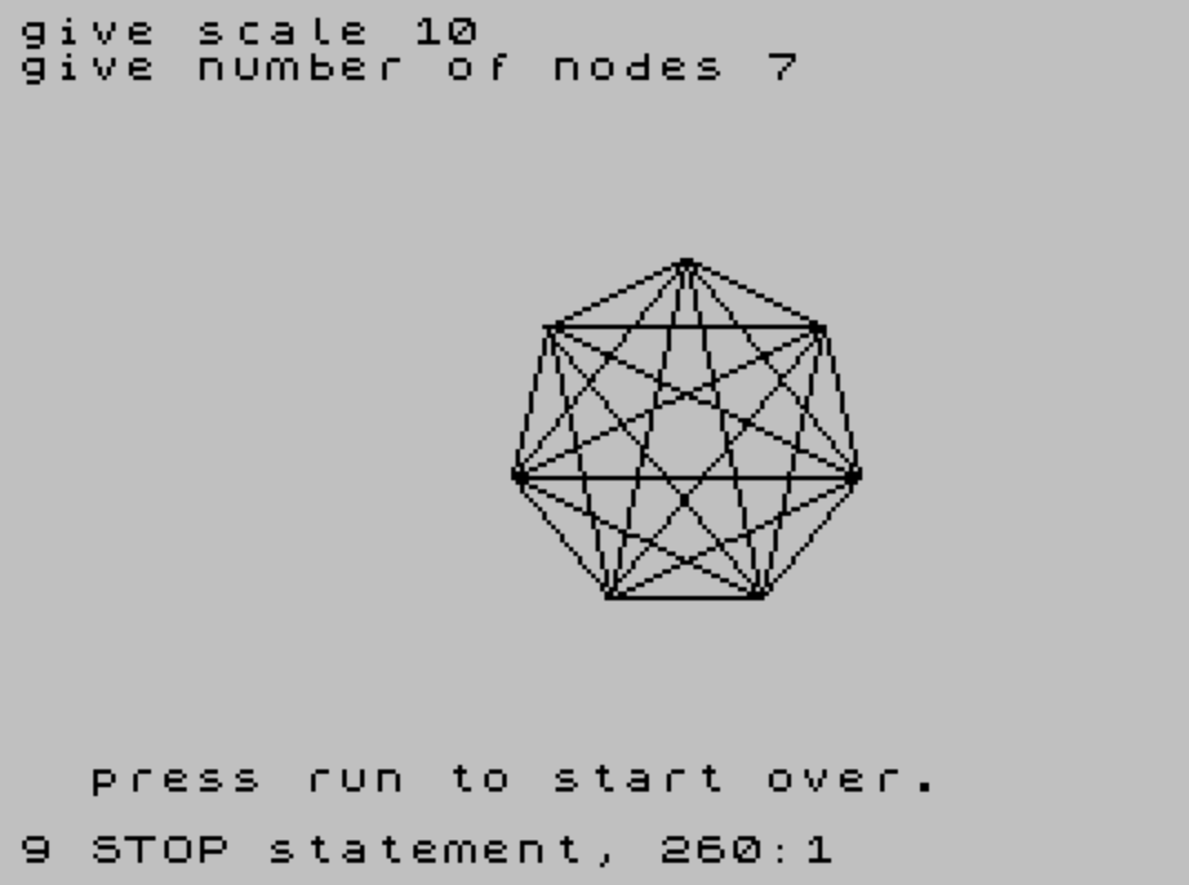
Source Code
  10 DIM x(60)
  20 DIM y(60)
  30 CLS
  40 PRINT "give scale ";
  50 INPUT s
  60 PRINT s
  70 PRINT "give number of nodes ";
  80 INPUT in
  90 PRINT in
 100 FOR i=1 TO in
 110 LET z=2* PI*i/in
 120 LET x(i)=4* SIN (z)+15
 130 LET y(i)=4* COS (z)+8
 140 NEXT i
 150 LET im=in-1
 160 FOR n=1 TO im
 170 LET ip=n+1
 180 FOR m=ip TO in
 190 PLOT s*x(n),s*y(n)
 200 LET dx=s*x(m)-s*x(n)
 210 LET dy=s*y(m)-s*y(n)
 220 DRAW dx,dy
 230 NEXT m
 240 NEXT n
 250 PRINT AT 21,2;"press run to start over."
 260 STOP
 270 SAVE "nodes" LINE 10
Note: Type-in program listings on this website use ZMAKEBAS notation for graphics characters.