
This program calculates the input impedance of a transmission line across a user-specified range of electrical distances expressed in degrees. For each angular step, it computes the complex impedance by combining the load impedance (with a reactive “J” component) and the characteristic line impedance using the standard transmission line equation involving the tangent of the electrical length. Rectangular-to-polar conversion via SQR and ATN yields the magnitude and phase angle, with a quadrant correction applied when the denominator phasor falls in the negative-real half-plane. Results are printed to both the screen and the printer, with a demo mode triggered by holding ENTER at startup that bypasses user INPUT prompts and suppresses printer output. The program also POKEs address 23692 to prevent the “scroll?” prompt from interrupting a long table of results.
Program Structure
The program is organized into a clear sequence of phases: initialization (lines 1–16), parameter input (lines 20–80), header output (lines 100–110), and a computation loop (lines 120–380), followed by a STOP at line 8999 and a SAVE at line 9000. The REM statements at lines 3, 4, 8, 14, 90, 130, 200, 220, 270, 290, 310, 330, and 350 are unusually verbose, serving as inline documentation for each logical section.
Demo Mode
A notable feature is the demo/bypass mode controlled by the FLAG variable. After a PAUSE 30 at line 12, line 16 checks INKEY$: if a key (specifically ENTER held from the RUN command) is still detected, the program skips all INPUT prompts and loads preset values (ZL=40, ZLJ=20, ZO=50, BS1=35, BS2=55, S=1), sets FLAG=1, and jumps directly to the output loop. When FLAG=1, lines 100, 360 use IF FLAG=1 THEN GO TO to bypass LPRINT statements, preventing spurious printer output during demo runs.
Transmission Line Calculation
The core formula implements the standard transmission line input impedance equation. For each angular distance L (in degrees), the tangent is computed at line 150 as TN = TAN(L * PI / 180). The numerator and denominator complex phasors are then assembled:
JPI = ZO * TN— reactive part of line termJTN = JPI + ZLJ— imaginary part of numeratorJTD = ZL * TN— imaginary part of denominatorZLD = ZO - (ZLJ * TN)— real part of denominator
The real part of the numerator is simply ZL, and the real part of the denominator is ZLD. Magnitudes are found via SQR at lines 230–240, and angles via ATN at lines 250–260.
Singularity Avoidance
Two guards prevent arithmetic errors. Line 140 skips L=90 and L=270 using NEXT L directly inside the FOR loop, avoiding the infinite tangent at those angles. Line 210 similarly skips iterations where ZLD=0, which would cause a division-by-zero when computing the denominator angle.
Quadrant Correction
Because ATN returns values only in the range −π/2 to +π/2, the angle of the denominator phasor AD is incorrect when the real part ZLD is negative (second or third quadrant). Line 280 corrects this by adding PI to AD when ZLD < 0, restoring the proper principal value for a phasor in the left half-plane.
Output Formatting
Both magnitude and phase are truncated (not rounded) to three decimal places using the INT(1000 * value) / 1000 idiom at lines 300 and 320. Line 340 POKEs the system variable at address 23692 with 255 inside the loop, resetting the scroll counter before each row is printed so the “scroll?” prompt never interrupts a long table.
Variable Summary
| Variable | Role |
|---|---|
ZL | Real part of load impedance |
ZLJ | Imaginary (“J”) part of load impedance |
ZO | Characteristic impedance of the line |
BS1, BS2 | Start and stop distances in degrees |
S | Step width in degrees |
FLAG | Demo mode flag (1 = demo, suppresses printer) |
TN | TAN of current angle |
MN, MD | Magnitudes of numerator and denominator phasors |
AN, AD | Angles of numerator and denominator phasors (radians) |
MAGNITUDE | Computed impedance magnitude, truncated to 3 d.p. |
PHASE | Computed phase angle in degrees, truncated to 3 d.p. |
Potential Anomalies
- The singularity check at line 140 handles only exact integer values 90 and 270. If
BS1,BS2, andSare chosen such that those values are never hit as exact loop iterations (e.g.,S=0.5starting at 35), the guard still works correctly, but non-integer near-singularities will produce very large but finite results without warning. FLAGis initialized to 0 at line 10 each run, so the demo mode cannot persist across runs without re-triggering the INKEY$ check — this is by design.- The
SAVEat line 9000 is unreachable during normal execution due to theSTOPat line 8999; it must be run manually or via directGO TO 9000.
Image Gallery
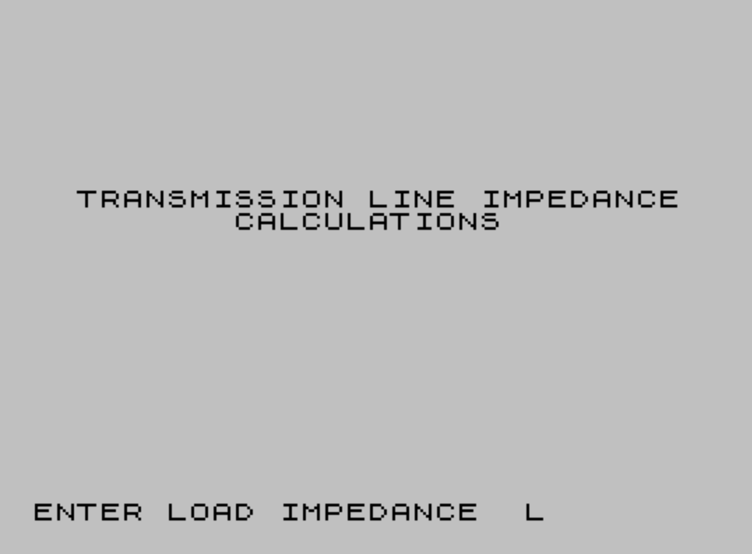
Source Code
    1 INK 0:PAPER 7:BORDER 7:CLS
    2 PRINT AT 9,2;"TRANSMISSION LINE IMPEDANCE", TAB 9;"CALCULATIONS"
    3 REM \{16}\{7}\* 1986 Ronald Ginardi\{16}\{0}
    4 \{16}\{2} REM Calculates impedance of     transmission line for suc-      cessive fractions of wave       lengths, shown as distance      in degrees.\{16}\{0}
    8 \{16}\{2} REM Initialize variable\{16}\{0}
   10 \{16}\{0} LET FLAG=0
   12 PAUSE 30
   14 \{16}\{4}\{16}\{3} REM This INKEY$ allows run-     ning program without enter-     ing all variables and when      doing so, does not print to     printer. Holding down ENTER     after RUN goes to these         preset demo variables. Not      holding down ENTER allows       normal operation. PAUSE         allows 30/60 sec to let up      on ENTER key.\{16}\{0}
   16 IF INKEY$ <>"" THEN LET ZL=40:LET ZLJ=20:LET ZO=50:LET BS1=35:LET BS2=55:LET S=1:LET FLAG=1:GO TO 100
   20 INPUT "ENTER LOAD IMPEDANCE  ";ZL
   40 INPUT "ENTER LOAD 'J' VALUE   ";ZLJ
   50 INPUT "ENTER LINE IMPEDANCE   ";ZO
   60 INPUT "ENTER START DEGREE DISTANCE   ";BS1
   70 INPUT "ENTER STOP DEGREE DISTANCE   ";BS2
   80 INPUT "ENTER STEP WIDTH   ";S
   90 \{16}\{4} REM This prints header on       screen as well as printer.      if not demo.\{16}\{0}
  100 PRINT "DISTANCE  IMPEDANCE   ANGLE":IF FLAG=1 THEN GO TO 120
  110 LPRINT "IMPEDANCE OF TRANSMISSION LINE  WITH THE FOLLOWING PARAMETERS"''"CHARACTERISTIC IMPEDANCE = ";ZO'"LOAD = ";ZL;" WITH A 'J' OF ";ZLJ'''"DISTANCE  IMPEDANCE   ANGLE"
  120 FOR L=BS1 TO BS2 STEP S
  130 \{16}\{4} REM This prevents dividing      by infinity.\{16}\{0}
  140 IF L=90 OR L=270 THEN NEXT L
  150 LET TN= TAN (L* PI/180)
  160 LET JPI=ZO*TN
  170 LET JTN=JPI+ZLJ
  180 LET JTD=ZL*TN
  190 LET ZLD=ZO-(ZLJ*TN)
  200 \{16}\{4} REM Prevents dividing by 0\{16}\{0}
  210 IF ZLD=0 THEN NEXT L
  220 \{16}\{4} REM Rectangular to Polar        conversion\{16}\{0}
  230 LET MN= SQR (ZL*ZL+JTN*JTN)
  240 LET MD= SQR (ZLD*ZLD+JTD*JTD)
  250 LET AN= ATN (JTN/ZL)
  260 LET AD= ATN (JTD/ZLD)
  270 \{16}\{4} REM Corrects for polar con-     version method when angle       is in second quadrant.\{16}\{0}
  280 IF ZLD<0 THEN LET AD=AD+ PI
  290 \{16}\{4} REM Solves for magnitude of     vector and modifys for dis-     play.\{16}\{0}
  300 LET MAGNITUDE= INT (1000*ZO*MN/MD)/1000
  310 \{16}\{4} REM Solves for phase angle,     converts radians to degrees     and modifys for display.\{16}\{0}
  320 LET PHASE= INT (1000*(AN-AD)*180/ PI)/1000
  330 \{16}\{1} REM Stops screen from stop-     ping and asking "scroll?"\{16}\{0}
  340 POKE 23692,255
  350 \{16}\{4} REM Prints to screen, and       skips over printer if only      demo program\{16}\{0}
  360 PRINT L;"           ";MAGNITUDE;"   ";PHASE:IF FLAG=1 THEN GO TO 380
  370 LPRINT L;"           ";MAGNITUDE;"   ";PHASE
  380 NEXT L
 8999 STOP
 9000 SAVE "XMSLIN.BA" LINE 1
Note: Type-in program listings on this website use ZMAKEBAS notation for graphics characters.