
Editor: Syd Wyncoop has contributed an excellent article called “A STUDY IN NUMBERS”. Due to space limitations in this issue, we will run it next time. The article discusses many of the number systems (bases) that are used by computer programmers, such as Decimal, Binary, and Hexadecimal. Hopefully, this will bring in to focus and act as a compendium for students of our “machine code class”, but also should be of interest to all.
Before we begin, I need to ask again for some feedback from you. Especially if you are a TS1000 user. I have heard from no TS1000 users and will concentrate the programming on the 2068 if you don’t speak up! The MC instructions are the same for both computers however, each program must be tailored to the operating system. This makes writing this series more difficult. Also, I need your ideas. What would you like to see? We are near done with Z80 instructions.
Let’s talk about the logical instructions, And, Or and Xor. And and Or do not give the true/false response you are familiar with if you have used them as Basic boolean operators. Instead, they and Xor operate on the individual bits of a register, or other 8 bit location. Also, the flags are always affected according to the result of these instructions.
Chart 10 provides the truth tables that explain how each of the logical instructions affects the bits being operated upon. While this makes the individual operations clear, it does little to help you understand the instruction, And F0h, when it is encountered. In order to understand these instructions better, it is neccessary to understand a little of Base 2 (binary) numbers.
Hex/Bin Conversions
Hex   Bin    ! Hex   Bin
 0    0000   !  8    1000
 1    0001   !  9    1001
 2    0010   !  A    1010
 3    0011   !  B    1011
 4    0100   !  C    1100
 5    0101   !  D    1101
 6    0110   !  E    1110
 7    0111   !  F    1111
Truth Tables
    And               Or                Xor
___!_0_!_1_      ___!_0_!_1_      ___!_0_!_1_
_0_!_0_!_0_      _0_!_0_!_1_      _0_!_0_!_1_
_1_!_0_!_1_      _1_!_1_!_1_      _1_!_1_!_0_
As we discovered in our discussion of hex numbers, the highest digit in any base is equal to base-1. This means that we have 2 digits in binary, 0 and 1. The typical number 240 or F0h is 11110000b in binary. The b denotes a binary number just as our h means hex.
Rather than provide a full decimal to binary conversion chart, I have given you a hex to binary chart. This is because we have been working with hex numbers which are a very good shorthand for binary. Eight digit binary numbers are very easily represented by two digit hex numbers. I have provided program 1 for those of you wishing to generate your own charts.
I think you will agree that all those 1’s and 0’s of binary are begging for us to make an error. That being true, why do we want to represent numbers in binary? The reason is because the logical instructions operate on individual bits and these bits can be easily represented as set or reset (on or off, if you prefer) which is 1 or 0, respectively. Binary provides an easy way for us humans to determine how our friend CPU will act.
Let’s look at And. And is often used to mask off unwanted bits. Suppose our routine puts the result in the accumulator and we want to insure that the result is never greater than 7. We would do this with the instruction, And 07h. If A contains 52h, the And 07h would make A contain 02h.
  A = 01010010 = 52h
And   00000111 = 07h
  A = 00000010 = 02h
The result is always placed back in the A register. We have effectively said we only want to know about the three least significant bits of A, therefore we have discarded the rest.
Or is used to set the bits we need. If we wanted to insure the most significant bit is set we would Or 80h. If we wanted to insure the most significant bit is reset, we would And 7Fh. Can you see where 10000000b and 01111111b are more useful than 80h and 7Fh with these instructions? Binary allows you to see exactly what is happening.
 A = 01010010 = 82h          A = 01010010 = 82h
Or   10000000 = 80h        And   01111111 = 7Fh
 A = 11010010 = D2h          A = 01010010 = 82h
Chart 11
Logical______________________!_Rotate and Shift_____________
And r                        ! Rlca
And n                        ! Rla
And (HL)                     ! Rrca
Or r                         ! Rra
Or n                         ! Rlc r
Or (HL)                      ! Rlc (HL)
Xor r                        ! Rl r
Xor n                        ! Rl (HL)
Xor (HL)                     ! Rrc r
                             ! Rrc (HL)
                             ! Rr r
Bit Manipulation_____________! Rr (HL)
Bit b,r                      ! Sla r
Bit b,(HL)                   ! Sla (HL)
Set b,r                      ! Sra r
Set b,(HL)                   ! Sra (HL)
Res b,r                      ! Srl r
Res b,(HL)                   ! Srl (HL)
                             ! Rld
                             ! Rrd
An example of using Or would be when we want to calculate an address. We would calculate the offset in A and then Or it with the high byte of the address to complete the calculation.
Xor is not a fugutive from the Outer-limits! It is a special case that sets only those bits that differ. For example:
  A = 10010110 = 96h
Xor   01011101 = 5Dh
  A = 11001011 = CBh
This is referred to as complimenting. Xor is complicated and is not used often but it is handy at times.
The bit manipulation instructions are the largest single group of Z80 instructions. They are Set, Res and Bit. They are easily understood as they set, reset or test the status of any bit in any register or address.
Set and Res are the set and reset instructions respectively and they do not affect any flags. These instructions are useful when you need to set/reset a bit without affecting the other bits in that byte. You could use And and Or to accomplish the same task but often you will not know the status of the other bits. Set and Res avoid this problem.
Bit is the test instruction. The bits are unchanged but the Zero flag is used to indicate the results of the test. The flag is set if the tested bit is zero, and reset if the bit is one.
The rotate and shift instructions are also bit manipulation instructions. They are classified separately as they operate on the entire byte. Many of them use the Carry flag to store a bit.
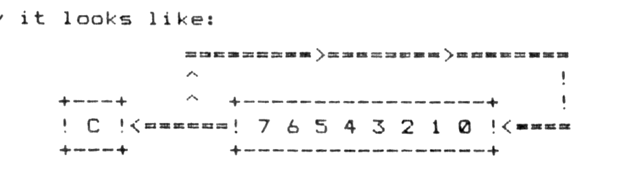
Rlca rotates the contents of the accumulator left one bit, placing the sign (most significant) bit in Carry as well as in bit 0. The effect of this instruction is to multiply A by 2. For example:
11001000b becomes 10010001b
Graphically it looks like:
Program 1
 10 LPrint "Dec  Hex  Bin"
 20 For i=0 to 255
100 Let h$="  "
110 Let h1=Int (i/16)
120 Let h$(1)=Chr$ (h1+48+(7 And h1>9))
130 Let h2=i-h1*256
140 Let h$(2)=Chr$ (h2+48+(7 And h2>9))
200 Let b$="00000000"
210 Let a=i
220 For n=7 to 0 Step -1
230 If (a-2*Int (a/2)) Then Let b$(n+1)="1"
240 Let a=Int (a/2)
250 Next n
300 Let t=(1 And i<10)+(1 And i<100)+(0 And i<1000)
310 LPrint Tab t;i;Tab 5;h$;Tab 10;b$
320 Next i
TS1000 users need to change the following lines:
120 Let h$(1)=Chr$(h1+28)
140 Let h$(2)=Chr$(h2+28)
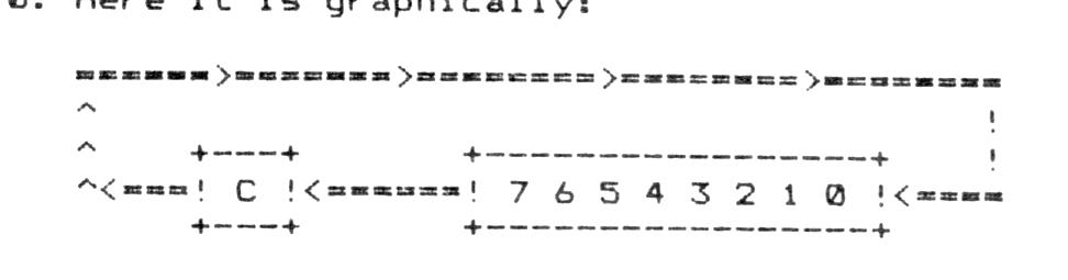
Rla rotates the accumulator bits left though Carry. The Carry flag still contains bit 7 but the prior Carry flag is now in bit 0. Here it is graphically:
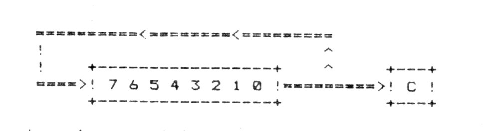
Rrca is similiar to Rlca. This time the accumulator’s bits are rotated right. Bit 0 is copied into Carry and bit 7. The effect of this instruction is to divide A by 2. This one looks like:
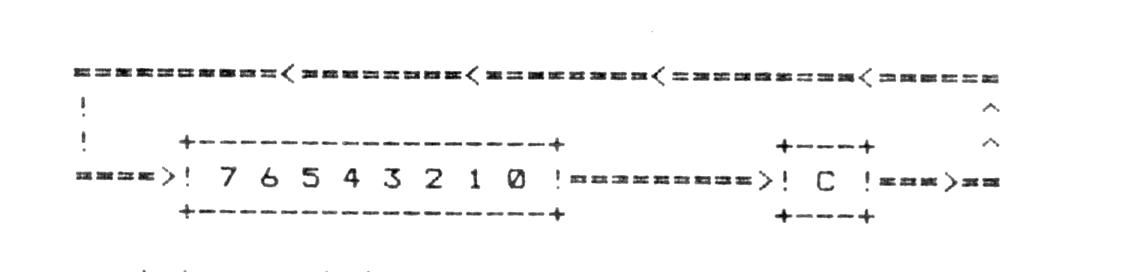
Rra is not surprisingly like Rla, except that we are rotating right. Bit 0 is rotated through the Carry flag. Here it is:
The remaining rotate instructions will operate on any register (including A) or the contents of any address. Rlc r is graphically the same as Rlca. Rl r is graphically the same as Rla. Rrc r is graphically the same as Rrca. Rr r is graphically the same as Rra. The difference between Rra and Rr A is that Rra affects only the Carry flag while Rr A affects all the flags.
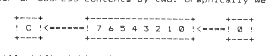
The shift instructions are the true arithmetic instructions although they are otherwise similiar to the rotate instructions. The first, Sla is similiar to Rlc instruction, except that the least significant bit becomes zero. The effect is to multiply the register or address contents by two. Graphically we have:
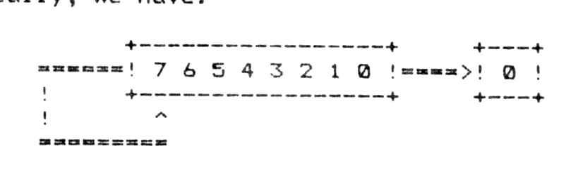
Sra will shift right arithmetic the bits in the specified register or address. This is similiar to Rrc except that bit 0 is only copied to the Carry flag. Bit 7 remains as it was. The effect of this is to divide signed numbers by two, leaving the carry set if there was a remainder (you were dividing an odd number). Graphically, we have:
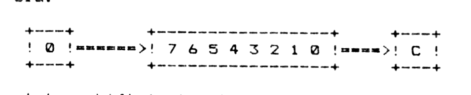
Srl, or shift right logical is the same as Sra, except that the most significant bit becomes zero. Graphically, this is the reverse of Sla:
The last two shift instructions, I have never found a use for. They are Rld and Rrd, which mean rotate left decimal and rotate right decimal, respectively. They operate on the contents of the memory location addressed by HL and the accumulator.
In the case of Rld (not to be confused with Rl d) the low nybble of (HL) is copied into the high nybble of (HL), the high nybble of (HL) is copied into the low nybble of the accumulator, and the low nybble of the accumulator is copied into the low nybble of (HL). Got it? Here’s a picture:
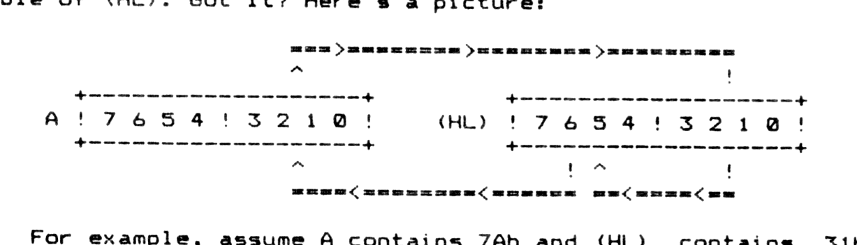
For example, assume A contains 7Ah and (HL) contains 31h. After an Rld instruction, A will contain 73h and (HL) will contain 1A.
Rrd behaves just as obnoxiously except, of course, that the rotation is to the right. Here it is:
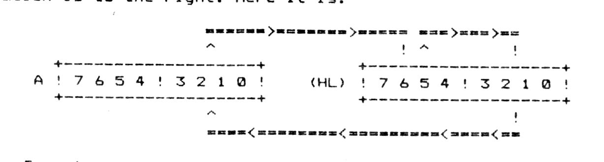
Remember, you will be limited to an eight bit answer with these instructions. The Carry flag will indicate an overflow and the accumulator, register or memory location will contain the difference. In other words, all arithmetic results will be modulo 256.
Now, how about a practical application? Let’s develope a hex dump routine. We can show any byte as two hex digits once we know where to begin. We need the Basic interface first:
Hex Dump Interface
 10 Print "Dump from decimal address: ";
 20 Input a
 30 Print a
 40 Print
 50 Poke base-1,Int (a/256)
 60 Poke base-2,a-Int (a/256)*256
 70 Rand Usr base
 75 Rem base=address of Hex Dump,substitute your addresses for base
 80 If Inkey$="" Then Goto 80
 90 If Code Inkey$=13 Then Goto 70
 95 Rem 13=Enter on the TS2068
    Use 118 on the TS1000
100 If Inkey$="Z" Then Copy
110 Goto 80
And now the Hex Dump routine for the TS2068. Remember to use your addresses in place of the xxxx.
          Store    Equ HexDmp-2
FDCB0286  HexDmp   Res 0,(TVFlag)    ;this bit tells the Rom
                                     ;routine to print in the
                                     ;main screen area
2Axxxx             Ld HL,(Store)     ;get address to begin dump
0E10               Ld C,10h          ;counter-# of lines to dump
7C        OutrLp   Ld A,H            ;get the high byte of the
                                     ;first address in this line
                                     ;of the dumped bytes
CDxxxx             Call HexPrt       ;go print it
7D                 Ld A,L            ;get low byte of address
CDxxxx             Call HexPrt       ;go print it
3E20               Ld A,20h          ;ascii space
F5                 Push AF           ;save the space character
D7                 Rst 10h           ;print the space
F1                 Pop AF            ;retrieve the character
D7                 Rst 10h           ;print another space
0608               Ld B,08h          ;counter-# bytes/line
7E        InnrLp   Ld A,(HL)         ;byte to accumulator
CDxxxx             Call HexPrt       ;go print it
3E20               Ld A,20h          ;ascii space
D7                 Rst 10h           ;print the space
23                 Inc HL            ;advance byte pointer
10F6               Djnz,InnrLp       ;loop for 8 bytes
3E0D               Ld A,0Dh          ;ascii carriage return
D7                 Rst 10h           ;go to start of next line
0D                 Dec C             ;count one line done and
20E0               Jr nz,OutrLp      ;loop for 16 lines
22xxxx             Ld (Store),HL     ;store start of next line
C9        Done     Ret               ;return to basic

F5        HexPrt   Push AF           ;save it
E6F0               And F0h           ;mask off high nybble
1F                 Rra               ;and rotate to low nybble
1F                 Rra
1F                 Rra
1F                 Rra
CDxxxx             Call Print        ;go print digit in A
F1                 Pop AF            ;retrieve it
E60F               And 0Fh           ;mask off low nybble
CDxxxx             Call Print        ;go print digit in A
C9                 Ret               ;ret to calling routine

FE0A      Print    Cp 0Ah            ;check if digit is greater
                                     ;than 9
3F                 Ccf               ;if so, set carry and
DCxxxx             Call c,Offset     ;go adjust for correct
                                     ;ascii character codes
C630               Add A,30h         ;make a printable char code
E5                 Push HL           ;save registers
C5                 Push BC
D7                 Rst 10h           ;Rom print routine
C1                 Pop BC            ;restore registers
E1                 Pop HL
C9                 Ret               ;return to calling routine

C607      Offset   Add A,07h         ;adjust digit to skip over
                                     ;ascii characters between
                                     ;9 and A
C9                 Ret               ;return to calling routine
And for you TS1000 owners (I still use mine!):
2A7B40    HexDmp   Ld HL,(Store)     ;get address to begin dump
0E10               Ld C,10h          ;counter-#of lines to dump
7C        OutrLp   Ld A,H            ;get the high byte of the
                                     ;first address in this line
                                     ;of the dumped bytes
CDA940             Call HexPrt       ;go print it
7D                 Ld A,L            ;get low byte of address
CDA940             Call HexPrt       ;go print it
AF                 Xor A             ;same as Ld A,00h
F5                 Push AF           ;save the space character
D7                 Rst 10h           ;print the space
F1                 Pop AF            ;retrieve the character
D7                 Rst 10h           ;print another space
0608               Ld B,08h          ;counter-# bytes/line
7E        InnrLp   Ld A,(HL)         ;byte to accumulator
CDA940             Call HexPrt       ;go print it
AF                 Xor A             ;get space character
D7                 Rst 10h           ;print the space
23                 Inc HL            ;advance byte pointer
10F7               Djnz,InnrLp       ;loop for 8 bytes
3E76               Ld A,76h          ;get carriage return char
D7                 Rst 10h           ;go to start of next line

0D                 Dec C             ;count one line done and
20E2               Jr nz,OutrLp      ;loop for 16 lines
227B40             Ld (Store),HL     ;store start of next line
C9        Done     Ret               ;return to basic

F5        HexPrt   Push AF           ;save byte
E6F0               And F0h           ;mask off high nybble and
1F                 Rra               ;rotate to low nybble
1F                 Rra
1F                 Rra
1F                 Rra
CDBA40             Call Print        ;go print digit in A
F1                 Pop AF            ;retrieve byte
E60F               And 0Fh           ;mask low nybble
CDBA40             Call Print        ;go print it
C9                 Ret               ;return to calling routine

C61C      Print    Add A,1Ch         ;make a character 0 to F
E5                 Push HL           ;save registers
C5                 Push BC
D7                 Rst 10h           ;Rom print routine
C1                 Pop BC            ;restore registers
E1                 Pop HL
C9                 Ret               ;return to calling routine
I have to assume that if you are still with me, you have obtained some good study aids. Since almost all books on the subject of Z80 MC have numerous tables in them, this is the last time I will give the hex codes in the MC disassemblies. I will instead, provide the source code. What’s source code? That’s another lesson. See ya soon!
Note: Type-in program listings on this website use ZMAKEBAS notation for graphics characters.